Sunday 29 April 2012

Primary Slider Clamp

Todays horrible weather gave me a good excuse to do some more work on the Tesla. My next task is to make some kind of easily moveable clamp for the outer connection to the primary coil. It needs to be easily moveable so you can adjust its position (tap point) on the primary coil. The position of the clamp on the primary coil determines the energised length of the primary coil and hence its resonance. The tap point is moved so you can adjust the resonance of the primary to match that of the secondary coil. Well there's the basic tech stuff, here's how I made the clamp.
I started off with a chunk of copper that I picked up off ebay for about £8. It was about 3" long, 1" wide and 3/8" thick. The clamp would have to be of an unusual design because of the perspex disc that covers the whole of the primary coil. I will have to clamp onto the primary coil from below and, depending on the eventual tap point, may have restricted access due to the perspex disc underneath the primary.
After taking a few measurements I made a quick drawing using iDraw on my MacBook just to work out if this design was feasible. I decided this design should work even if the tap point is in the more inaccessible places on the primary coil. The length and shape of the righthand end of clamp may change as the design develops.
The copper block was marked up and sawn into the rough shapes required. The parts were cut slightly larger than required as they would be milled down to the required dimensions.
The off-cut removed was marked up to form the second part and roughly sawn out again oversize to allow for milling.
I fitted a 10mm milling bit and did the first lengthways run to produce the correct thickness required (6mm).
Here's a vid of a bit of the milling process. Milling copper is pretty easy as it's quite soft, I had to use the milling vice because the small height of the pieces I was working on. It's good practice to clamp work as close to the milling bed as possible so any slop in the bed is reduced to a minium. I couldn't do this with these pieces so I kept cut depths small.
After milling the two pieces were clamped together and drilled at the intersect to form the clamp jaws. The primary coil is 1/4" tubing so I used a 1/4" drill bit to form the jaws. To get the jaws to clamp tight on the tube I will remove some of the material at the vertical intersect just below the drilled hole.
A test fit of the piece works fine. It's a tight fit between the coil and the perspex disc underneath so I will mill another 0.5mm off the bottom of the lower assembly.
This picture really shows the need for this particular design of clamp especially if the tap point lies inside the external diameter of the primary coils support disc. Next session I will reduce the clamp thickness, join the two pieces together with some kind of slide mechanism and add the electrical connection.

If you like this blog you can show your support by one or all of these. 1. +1 my blog and email it to a friend. 2. Follow me.... It's good to know someones interested. 3. Leave a comment.... All are appreciated.

Tuesday 24 April 2012

Electrical connection to the Primary Coil

A few weeks back I made a very nice copper clamp pin which would be used to connect the inner end of the primary coil to the HT lead from the synchronous spark gap (SSG).
The hole at the top will accomodate the inner end of the primary coil and the threaded section will pass through a hole in the primary coil support disc and then the electrical lug will accept the HT lead to the SSG.
First job today was to drill the hole for this clamp pin.
The picture above clearly shows the primary coil support disc, it's the white disc sitting under the radial primary combs. It's white as it still has its protective coating and a layer of masking tape. To drill the hole needed I would need to remove this disc so after marking the hole position I started disassembly. I removed the toroid, the secondary coil and the primary coil assembly which only took a few minutes. The primary coil support disc was removed by undoing the 8 allen key bolts (stainless of course) that screw through the disc into the perspex support columns. I drilled  the 9mm hole required for the clamp pin and then removed all the protective coating from the primary coil support disc.
The primary support disc was refitted and the clamp pin slipped over the inner end of the primary coil and the grub screws tightened. The primary coil assembly was then lowered down onto the support disc making sure the clamp pin threaded end lined up with the clearance hole. It did!!
Above is a close look at the clamp pin in situ. Very happy with design, it allows an easily removable electrical connection to the primary coil.
A shot from underneath shows the copper lug bolted to the threaded end of the clamp pin.
I've done a few more pics of the assembled tesla base as this is the first time all protective coatings and masking tape have been removed.
And finally a full length shot with the secondary and toroid back in place.

If you like this blog you can show your support by one or all of these. 1. +1 my blog and email it to a friend. 2. Follow me.... It's good to know someones interested. 3. Leave a comment.... All are appreciated.

Monday 23 April 2012

Fitting the phase shift Transformer

Another rather productive day. On holiday at the moment so spent a few more hours on the Tesla build. Today I managed to get the step down tansformer mounted in the base of the phase shift module.
As you can see it mounts directly onto the base disc. If you remember the step down transformer was originally mounted on the second level of the Tesla base. The pic below shows its original position.
I removed the whole module including the perspex base. After separating the transformer from the base I used the old base to mark drill points onto the base disc of the phase shift module. After drilling these holes I fixed the transformer to the base disc using the original ceramic pillars.
This left a couple of jobs to finish up. Two M12 flex glands were fitted by drilling two 10.7mm clearance holes and tapping out to 12mm. I also drilled six 12mm holes in the top disc, these are purely for ventilation. There are 7 similar holes in the base around the transformer and as the base stands on small cork pads air should be able to circulate up through these holes and out the vent holes in the top.
I took a picture of the main power module and the phase shift module together just to show you how I have tried to design them with the same look.
Still have wiring to finish up and few other touches to the phase shift module but I think I have achieved a matching module.
Here's the module that replaces the repositioned step down module. It's a rather large 40microfarad capacitor and is part of the phase shift circuit.
The capacitor has a central M8 mounting bolt which screws into a vertical perspex 8mm thick square. This square is bolted to the perspex base and is reinforced by a secondary perspex square flush up against it and also bolted to the base.
Again, just a bit of wiring needed to finish off.

If you like this blog you can show your support by one or all of these. 1. +1 my blog and email it to a friend. 2. Follow me.... It's good to know someones interested. 3. Leave a comment.... All are appreciated.

Sunday 22 April 2012

Finishing the Phase Shift module casing

Hi Tesla fans. Today I spent several hours on the phase shift module case. Last post described marking out and drilling the top and bottom perspex discs. I've not been looking forward to the next task but today I decided to get on with it. The phase shift module will contain the 2 Amp Variac and the 110V step down transformer, this means the perspex tube required is quite tall at 195mm. This presents a problem as it's too tall to fit under the chuck of my mill/drill and that means I would have to freehand drill the holes to take the 3mm bolts that fasten the end discs onto the tube. Doesn't sound to bad? Well remember that the perspex tube walls are 5mm thick that only leaves 1mm either side of the 3mm bolts. Now thats why I haven't been looking forward to this. I picked 15mm long M3 socket head screws to use to bolt the top 8mm thick perspex to the tube. This meant they would only protrude 7mm into the tube walls and the holes required for tapping could be kept reasonably short. Drilling went pretty well. I taped the top disc to the tube end so I could use the pre-drilled holes in the disc. I found the best way to keep as vertical as possible was to stop frequently an reposition 90 degree to the work. That way I could try to keep vertical in multiple planes.
The resulting tap holes were pretty tidy, at least none of them had broke through the tube walls due to being so far off the vertical. The 8 shallow holes were tapped out to take the M3 bolts (stainless of course).
My last excuse for a lull in my Tesla activities was the purchase of a Sony PS Vita. This months excuse was a little more impressive, took a quick snap of it before attempting the holes for the base disc.
A Peugeot RCZ GT 200. Second childhood, third mid-life crisis. Whatever!!
The base was taped to the tube and drilling was just a re-run of the top. The base disc is black 5mm perspex, black as clear would be pointless for the base, slightly thinner than the top as the top needs extra thickness to support the carry handles.
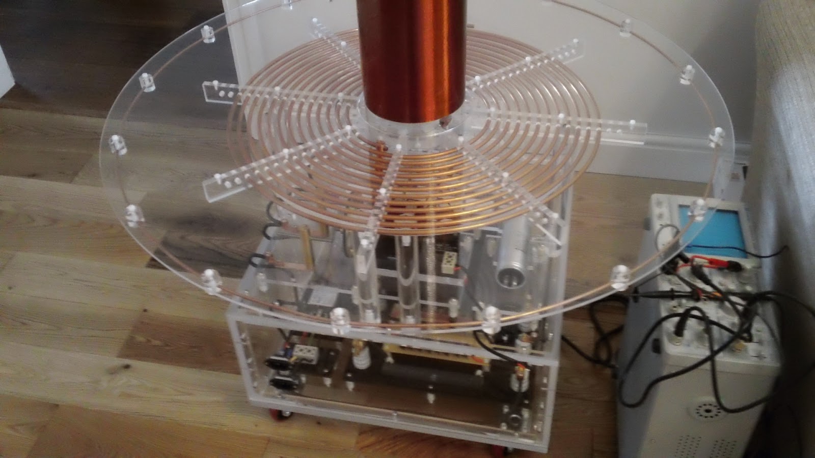
Here's the assembled phase shift module case. Next to it are a couple of lengths of 1/2" diameter aluminium rod. I will use these to make the carry handles. Below is a pic of the main power module containing the 10A Variac. I am trying to create the phase shift module in the same style.
The 2 aluminium rods were cut to 108mm and 17mm long flats were milled on each end. I drilled 6mm holes central on the flats on each end.

The handle will be supported on 22mm lengths of 6mm ID 8mm ED aluminium tubing. To allow the handles to sit flush on the tubes 8mm seats were milled on the underside of the handles centred on the 6mm mounting holes.
Below is an assembled handle. The supporting tubes fit nicely into the 8mm seats. I will be using socket head screws in the final asssembly (stainless of course).
I span up the handles on my lathe and used varying grades of emery clothes to create a nice brushed finish.
I fitted the 2A variac to the top disc incorporating the handles. The plastic bolts were the only long bolts I had to hand but I now know I need 4 60mm socket head bolts for the final assembly (stainless of course), off to ebay to source some.

If you like this blog you can show your support by one or all of these. 1. +1 my blog and email it to a friend. 2. Follow me.... It's good to know someones interested. 3. Leave a comment.... All are appreciated.