Monday 18 June 2012

New Toroid mount System

I have started work on the new toroid mounting system which differs in design from the method used on the first secondary coil. This time electrical connection to the toroid from the top of the secondary coil will not pass inside the coil form but will gently spiral around the mount and then finish as a copper disc which will be in direct contact with the underside of the toroid. The final system incorporates good secondary coil design taken from Stefan's Tesla Pages and the fast easy assembly of my first design.
Above is a quick sketch showing the basics of the new mount. Here we see 3 acrylic disc which are 107mm in diameter and 15mm  thick. The middle disc has an central 25mm hole. All bolts are nylon with the center bolt being M8 and the four others are M6. The diagram only shows the 2 side M6 bolts, there are another 2 front and rear. The bottom disc will be Tensoled to the top cap of the secondary coil and the four holes will be threaded to take the M6 bolts. The middle and top disc corresponding holes will be 6mm clearance holes with the top disc holes being countersunk. The central hole in the top disc will be threaded M8. The copper electrode disc will sit on top of the uppermost disc (probably bonded to it) and the the toroid mounts over the M8 bolt sandwiching the copper plate. The copper plate is soldered to the copper tail of the secondary with the tail gently spiralling (with some excess) around the toroid mount. This system will allow extra acrylic discs to be fitted to adjust the spacing between the toroid and the secondary coil.
I ordered four discs from Trent Plastics. The 3 required for the construction of the mount plus an extra to be inserted as a spacer. All the discs were the same apart from the one with the 25mm central cut-out. Above you can see the top 3 discs including the extra spacer. The lefthand disc has just been drilled to form the four 6mm clearance holes and the central hole which will be threaded to M8.
I the stacked the drilled disc on top of the other 2 and taped them tightly together. This allowed me to use the existing 6mm holes in the top disc as a template to drill 6mm clearance holes through the other 2 discs. After this was done I the added the fourth disc to the botton of the stack of disc, again taping it tightly to the others. I then passed the 6mm drill down each hole with just enough pressure to mark the center of the drill bit on the bottom disc. The stack was then separated and I could use the drill dimples on the surface of the bottom disc to centre the 5mm drill bit before drilling.
Here I am taping the four 5mm holes in the bottom acrylic disc to accept the M6 nylon bolts. Remember, this is the disc that will be bonded to the top cap of the secondary.
After removing all the protective masking tape I did a quick trial assembly just to make sure everything lined up OK.
And here's the mount in situ, not bonded yet, that will have to wait till the secondary is wound. That's the next job.

If you like this blog you can show your support by one or all of these. 1. +1 my blog and email it to a friend. 2. Follow me.... It's good to know someones interested. 3. Leave a comment.... All are appreciated.

Sunday 17 June 2012

Making the Second Tesla Secondary Coil

Well here we go with the build of the replacement secondary coil. Rather than jump straight in and build an identical secondary with thicker gauge wire and hence less turns I decided to do a little more homework on secondary coil designs. One thing had always concerned me with the design of the first secondary I built. This was the termination of the ends of the coil inside the secondary form. The top and bottom copper tails pass through small holes drilled in the wall of the secondary form and make electrical connection through the top and bottom end caps.
The pic above shows the top electrical connection on the old secondary coil. You can see the copper tail clamped into the lug underneath the perspex cap. A very neat set-up but nearly every knowledgeable Tesla site I have seen strongly advises against this. The only one who seems to prefer this method is Alan at teslastuff.com who has had great success with this design. My final decision on the design of the new coil was strongly influenced by a page at www.capturedlightning.org. Stefan really seems to know his stuff when it comes to design and build of secondary coils so I decided to proceed using many of his recommendations.
The overall length and diameter of the new coil form was the same and again it would be made from 150mm diameter 3mm thick clear acrylic tubing with top and bottom caps in 15mm thick clear acrylic. The new secondary will mount to the existing 8 mount holes in the tesla base unit so the secondary base cap is an exact copy of the original. If you want to see the original post showing construction of this you can find it here.
The pic above shows the new secondary coil form with the top and bottom caps in place.
Here is a close-up of the bottom cap of the secondary showing the 8 nylon bolts that pass through mounting holes in the primary coil support disc. The central hole is 10mm in dameter and will only be used to thread the whole form onto my winding jig. After winding the hole will be permanently sealed by a turned acrylic peg turned (very successfully) on my lathe.
The peg is a really close fit and the flat area will provide a good surface to be bonded with Tensol 12.
Above you can see a trail fit of the peg. Obviously it will be fitted on top of the base cap. The coil form is now ready to wound on the winding jig. However, not tonight, time for a quick spin in the new RCZ. Spot the new wheels.

If you like this blog you can show your support by one or all of these. 1. +1 my blog and email it to a friend. 2. Follow me.... It's good to know someones interested. 3. Leave a comment.... All are appreciated.

Tuesday 5 June 2012

Secondary Coil (Take 2)


A couple of weeks back I spent a few of hours playing with my oscilloscope. I had seen a few articles on the web showing how to measure the resonant frequency of the primary and secondary coils with an oscilloscope so I thought I would give it a try. The easiest one to measure is the secondary coil, to do it accurately you need to remove the primary coil and simulate streamers from the toroid as these change the resonant frequency. I was not looking for this degree of accuracy at this stage, really just having a go to get a rough idea.
I disconnected the earth lead from the bottom of the secondary coil and connected the coil to the signal generator built in to my oscilloscope.
I plugged a probe into channel one and Damien held the it approximately 3 feet away from the secondary coil.
I set the signal generator to a sine wave of 5v amplitude and starting at 100kHz as I guessed resonance should be between in the range 100kHz to 200 kHz.
The volts per division on channel 1 was set to 10mv and time/div set to 1us. I began to slowly increase the frequency of the signal being supplied to the secondary coil. You can see from the pic above that the trace was flat as 128kHz was passed. This remained the case most of the time as the frequency was increased, there were some signals picked up, presumably harmonics of the true resonance. To my amazement at 175.4kHz the flat trace suddenly transformed into a perfect sine wave, signifying we had hit the resonant frequency of the secondary coil.
As I said this was only done for experimental reasons and in no way to get an accurate resonant frequency, but it did get me thinking more about the relationship between the secondary and primary coils. I had read a lot of references to JAVATC while looking for information about Tesla coil tuning. It's a website based program used to help in the design of Tesla coils. It works by entering lots of component specs and various physical dimensions of the Tesla coil you have built or plan to build. When the program is run it calculates the resonant frequencies of the primary and secondary coil and displays the %tune between them. It can also be used to automatically tune the primary coil to the secondary, in this mode the program will output the correct tap point on the primary (in number of turns) to get resonance with the secondary. It took me a while to work out and gather all the different data required to test my own Tesla coil build but after a lot of measuring I entered the data into JAVATC.

CRAP!!!
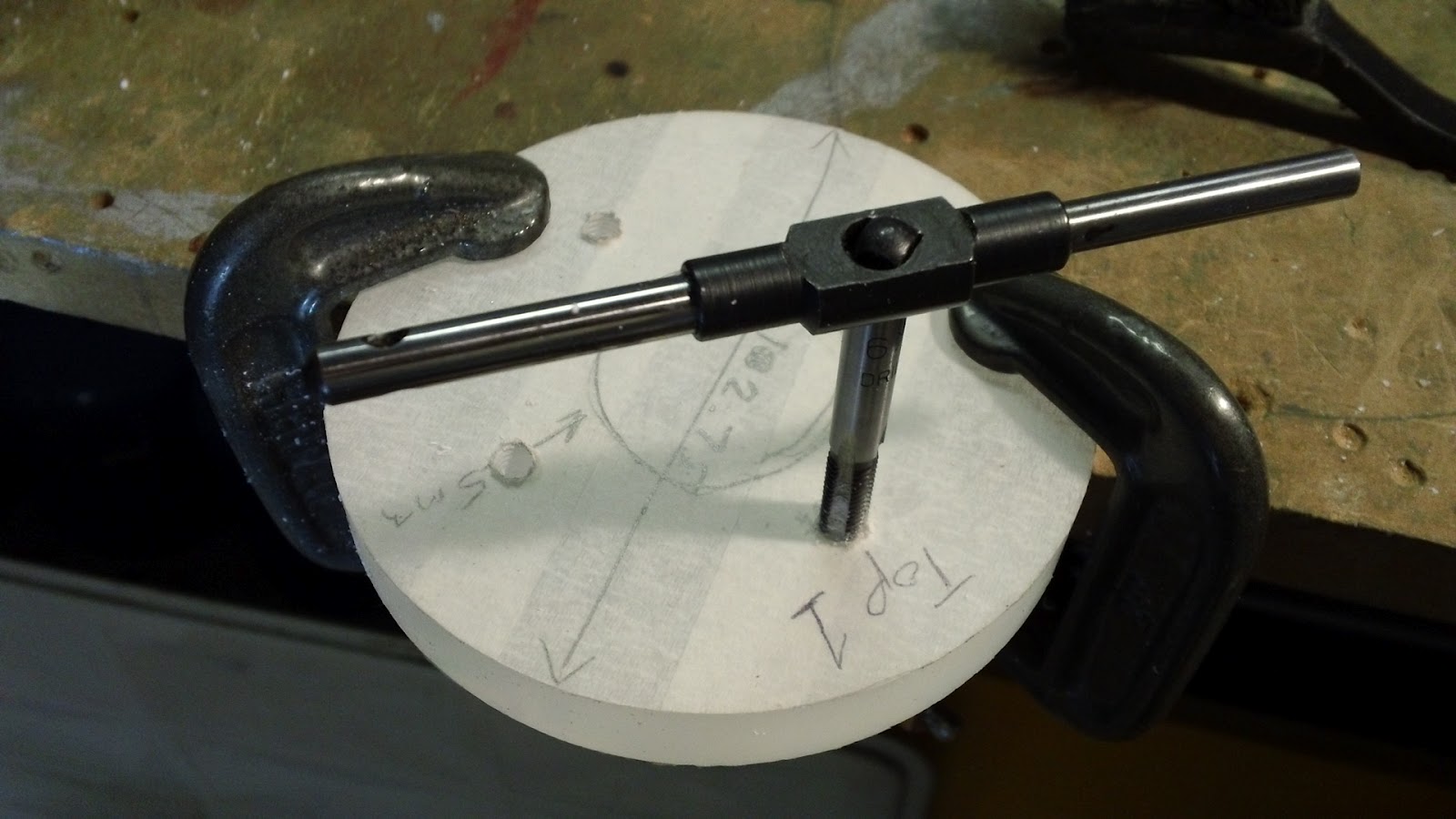
According to the software I needed to tap my primary coil at turn 16 to get resonance with the secondary coil. That would be a slight problem. I only have 12.5 turns on my primary!!! The reason for this was a lack of understanding when turning my secondary coil. I had opted for a larger secondary coil during the build after choosing a few other upgrades. I had failed to upgrade the magnet wire gauge used to form the windings. The 0.4mm diameter wire I used on the larger secondary had resulted in far more turns than required. There is only one thing for it, build another secondary with less turns.

If you like this blog you can show your support by one or all of these. 1. +1 my blog and email it to a friend. 2. Follow me.... It's good to know someones interested. 3. Leave a comment.... All are appreciated.