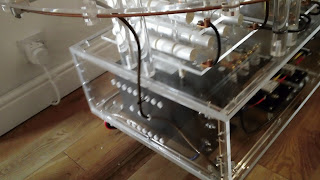
All was fine so I proceeded. I plugged the main power supply module into the mains and connected the phase shift module to it. Then connected the phase shift module to the SSG circuit iec socket on the side of the main tesla base module. The main supply to the neon transformer was left disconnected as, at this stage, I only want to test the SSG circuit.
Turned the phase shift module to its minimum setting, a final check then I threw ON/OFF switch.
The SSG motor hummed into life and spun up to full speed very quickly. I sat and watched for a while. Nothing seemed to be smoking or melting and the motor was running smooth. There was virtually no vibration, the electrode disc seemed to be balanced very well. I decided to give the phase module a try and rotated the variac knob a few degrees. Obviously there was no viewable change to the rotation of the SSG but I could hear the motor lose and regain its lock on the frequency each time I changed the position of the phase shift variac (well I think that's what I was hearing). On further increasing the phase module the SSG motor would completely lose lock and stop but regain and restart when the setting was reduced. By this time perspex case around the phase shift module was starting to cloud up with what looked like condensation. A good time to end this first test run.
After unplugging and further inspection I concluded that the fogging was just solvent being driven out of the varnish on the coil windings in the phase shift module.
I wanted a visible confirmation that I was actually achieving some degree of phase shift. First, I thought if I illuminated the SSG with a fluorescent strip light I might be able to "see" some phase shift as the phase shift module is adjusted due to the (50HZ) flashing of the strip light. Unfortunately no access to a strip light prevented that little test. After explaining what I was trying to achieve Damien came up with an idea. He could create a 50HZ strobe with a simple little program on an Arduino microcontroller.
Damien explains:
A 50Hz wave has a period of 0.02 seconds. This is composed of half-on and half-off output. Repeat this procedure and you get a fairly accurate 50Hz square wave. Hook this output to an LED and you have a simulated strip light running at 50Hz. While it isn't in phase with the mains (Unless you're really lucky when you turn on the Arduino!) and it's not massively accurate because of the inherent overheads introduced by the delays in the microcontroller and timers, it's a good way to get a strobing effect and get an idea whether the phase-shifter is working or not. Back to dad...
Here's a pic of the little unit Damien put together. We switched off the lights and fired up the SSG circuit.
Without adjusting the phase module the Arduino strobe was shone on the spinning electrode disc. The strobe effect worked well, the electrodes appeared to be rotating anticlockwise very slowly. This was due to the slight difference in frequency between mains and the Arduino strobe. If the frequencies were exactly the same the electrodes would appear static. I adjusted the phase shift module and this resulted in a change to the slow rotation of the electrodes. This change only occurred during the adjustment of the phase shift module. I think this pretty basic test is a good indication that there is a change in phase. Below is a video of the process, it's just about possible to see the moving electrodes as the phase module is adjusted, it was more obvious to the naked eye. I think the video camera frequency also combines with the other frequencies to complicate matters.
If you like this blog you can show your support by one or all of these. 1. +1 my blog and email it to a friend. 2. Follow me.... It's good to know someones interested. 3. Leave a comment.... All are appreciated.


