Today I decided to finish some of the electrical connections. Firstly I needed to complete some ground connections, 3 to be exact, and when I say ground I mean literally ground not mains earth ground. These are :-
1. Strike rail to ground.
2. Secondary coil to ground.
3. Neon transformer to ground.
I decided all 3 of the above will start from the ground post on the neon transformer as this has a large enough post to accomodate the multiple ring terminals.
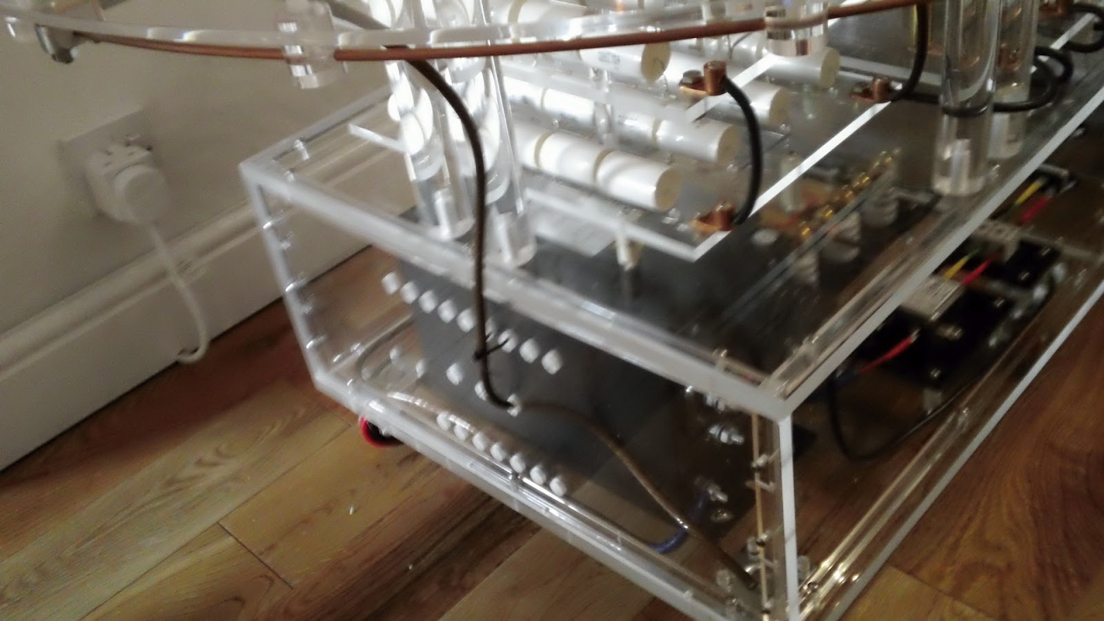
You can see this terminal in the pic above, it's the lower terminal with the blue sheathed wire attached. In this pic I have removed the perspex side panel.
As the 3 grounds will exit the lower level perspex box I needed to drill 3 holes in the perspex side panel. I masked up the side panel so to protect the perspex and so I could mark my drill points. The welding wire for the grounds is 8mm in diameter but I decided to drill 12mm holes so the wires could pass through with the ring terminals attached. This would make assembly and maintenance much easier.
The left hole would house the secondary coil connection, the right the strike rail connection and the centre would be to the grounding spike. I marked the top on the masking tape mainly to show this side is the outside as the panels do fit better one way than the other. I drilled the three 12mm holes and then removed the masking tape. But unfortunately failed to note which side was marked top. So I took my best guess and offered up the panel and proceeded to refit the mounting bolts. Guess what?
Wrong way! the bolts did not line up correctly and the result is shown above. The perspex corner post cracked. The bolts did feel a little tight, I should have realised the panel was the wrong way round. Took me an extra hour to make the replacement post.
Here's the side panel and new corner post back in situ. Now to make up the wire lengths required for the two ground connections.
The first is the strike rail connection. The wire end at the strike rail fastened inside a copper lug so I impregnated the copper strands with solder to stop the wire end disintegrating due to repeated clamping. The other end terminates in a ring terminal which was also soldered.
Next I did the ground connection to the lower end of the secondary coil. Both ends of this wire were fitted with ring terminals, again soldered.
Above you can see the routing and end connections of these two ground wires.
I am not going to fit the wire to the ground spike yet, there's no point as it will just get in the way. It will pass through the central hole in the side panel and attach to the ground post of the neon transformer thus connecting the neon transformer, strike rail and secondary coil to ground. The ground spike will be situated in the middle of my back lawn. It will consist of a 4 foot copper rod driven fully into the ground. I will run the connecting wire under the turf across the lawn and out on to the patio.
If you like this blog you can show your support by one or all of these.
1. +1 my blog and email it to a friend.
2. Follow me.... It's good to know someones interested.
3. Leave a comment.... All are appreciated.


No comments:
Post a Comment