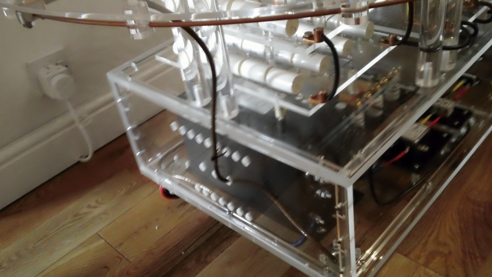
Finished off my homebuilt Tesla coil today. This involved finishing the primary coil sliding clamp. It required a way to clamp it to the primary coil and the fitting of an copper lug to make the electrical connection to the MMC bank.
The above pic shows the two parts of the clamp before adding a clamping mechanism. I wanted to keep this mechanism as simple as possible as I may redesign the whole clamp depending on the eventual tap point on the primary coil. I removed a 15mm length from the right hand end of the top piece and silver soldered it to the right hand end of the lower section. I then drilled a horizontal 2.5mm hole lengthways down the centre of the block which was tapped out to take an M3 allen bolt.
This produced a simple clamping method which still permits the two parts to separate to allow for repositioning. Adding a copper lug for the electrical connection just meant adding another threaded hole on the underside of the clamp.
I cut a 1.2m length of GTO wire to complete the electrical connection from the MMC bank to the clamp. 1.2m was needed so the clamp could reach any point around the primary coil. Each end of the GTO wire was coated in solder before fitting into the copper lugs. That's it Tesla coil finished, well almost. Have ordered a 33k ohm 2W resistor that I will fit across the terminals of the 40uF capacitor in the SSG circuit and bleed the stored charge away after each run of the Tesla coil, a simple safety feature.
If you like this blog you can show your support by one or all of these.
1. +1 my blog and email it to a friend.
2. Follow me.... It's good to know someones interested.
3. Leave a comment.... All are appreciated.
This is my blog of current hobbies, at the moment that happens to be all things Tesla so I have decided to build a Tesla coil and, as usual, I will go completely over the top with it.
Showing posts with label copper clamp. Show all posts
Monday, 7 May 2012
Sunday, 6 May 2012
Tesla coil ground connections
Today I decided to finish some of the electrical connections. Firstly I needed to complete some ground connections, 3 to be exact, and when I say ground I mean literally ground not mains earth ground. These are :-
1. Strike rail to ground.
2. Secondary coil to ground.
3. Neon transformer to ground.
I decided all 3 of the above will start from the ground post on the neon transformer as this has a large enough post to accomodate the multiple ring terminals.
You can see this terminal in the pic above, it's the lower terminal with the blue sheathed wire attached. In this pic I have removed the perspex side panel.
As the 3 grounds will exit the lower level perspex box I needed to drill 3 holes in the perspex side panel. I masked up the side panel so to protect the perspex and so I could mark my drill points. The welding wire for the grounds is 8mm in diameter but I decided to drill 12mm holes so the wires could pass through with the ring terminals attached. This would make assembly and maintenance much easier.
The left hole would house the secondary coil connection, the right the strike rail connection and the centre would be to the grounding spike. I marked the top on the masking tape mainly to show this side is the outside as the panels do fit better one way than the other. I drilled the three 12mm holes and then removed the masking tape. But unfortunately failed to note which side was marked top. So I took my best guess and offered up the panel and proceeded to refit the mounting bolts. Guess what?
Wrong way! the bolts did not line up correctly and the result is shown above. The perspex corner post cracked. The bolts did feel a little tight, I should have realised the panel was the wrong way round. Took me an extra hour to make the replacement post.
Here's the side panel and new corner post back in situ. Now to make up the wire lengths required for the two ground connections.
The first is the strike rail connection. The wire end at the strike rail fastened inside a copper lug so I impregnated the copper strands with solder to stop the wire end disintegrating due to repeated clamping. The other end terminates in a ring terminal which was also soldered.
Next I did the ground connection to the lower end of the secondary coil. Both ends of this wire were fitted with ring terminals, again soldered.
Above you can see the routing and end connections of these two ground wires.
I am not going to fit the wire to the ground spike yet, there's no point as it will just get in the way. It will pass through the central hole in the side panel and attach to the ground post of the neon transformer thus connecting the neon transformer, strike rail and secondary coil to ground. The ground spike will be situated in the middle of my back lawn. It will consist of a 4 foot copper rod driven fully into the ground. I will run the connecting wire under the turf across the lawn and out on to the patio.
If you like this blog you can show your support by one or all of these. 1. +1 my blog and email it to a friend. 2. Follow me.... It's good to know someones interested. 3. Leave a comment.... All are appreciated.
1. Strike rail to ground.
2. Secondary coil to ground.
3. Neon transformer to ground.
I decided all 3 of the above will start from the ground post on the neon transformer as this has a large enough post to accomodate the multiple ring terminals.
You can see this terminal in the pic above, it's the lower terminal with the blue sheathed wire attached. In this pic I have removed the perspex side panel.
As the 3 grounds will exit the lower level perspex box I needed to drill 3 holes in the perspex side panel. I masked up the side panel so to protect the perspex and so I could mark my drill points. The welding wire for the grounds is 8mm in diameter but I decided to drill 12mm holes so the wires could pass through with the ring terminals attached. This would make assembly and maintenance much easier.
The left hole would house the secondary coil connection, the right the strike rail connection and the centre would be to the grounding spike. I marked the top on the masking tape mainly to show this side is the outside as the panels do fit better one way than the other. I drilled the three 12mm holes and then removed the masking tape. But unfortunately failed to note which side was marked top. So I took my best guess and offered up the panel and proceeded to refit the mounting bolts. Guess what?
Wrong way! the bolts did not line up correctly and the result is shown above. The perspex corner post cracked. The bolts did feel a little tight, I should have realised the panel was the wrong way round. Took me an extra hour to make the replacement post.
Here's the side panel and new corner post back in situ. Now to make up the wire lengths required for the two ground connections.
The first is the strike rail connection. The wire end at the strike rail fastened inside a copper lug so I impregnated the copper strands with solder to stop the wire end disintegrating due to repeated clamping. The other end terminates in a ring terminal which was also soldered.
Next I did the ground connection to the lower end of the secondary coil. Both ends of this wire were fitted with ring terminals, again soldered.
Above you can see the routing and end connections of these two ground wires.
I am not going to fit the wire to the ground spike yet, there's no point as it will just get in the way. It will pass through the central hole in the side panel and attach to the ground post of the neon transformer thus connecting the neon transformer, strike rail and secondary coil to ground. The ground spike will be situated in the middle of my back lawn. It will consist of a 4 foot copper rod driven fully into the ground. I will run the connecting wire under the turf across the lawn and out on to the patio.
If you like this blog you can show your support by one or all of these. 1. +1 my blog and email it to a friend. 2. Follow me.... It's good to know someones interested. 3. Leave a comment.... All are appreciated.
Sunday, 29 April 2012
Primary Slider Clamp
Todays horrible weather gave me a good excuse to do some more work on the Tesla. My next task is to make some kind of easily moveable clamp for the outer connection to the primary coil. It needs to be easily moveable so you can adjust its position (tap point) on the primary coil. The position of the clamp on the primary coil determines the energised length of the primary coil and hence its resonance. The tap point is moved so you can adjust the resonance of the primary to match that of the secondary coil. Well there's the basic tech stuff, here's how I made the clamp.
I started off with a chunk of copper that I picked up off ebay for about £8. It was about 3" long, 1" wide and 3/8" thick. The clamp would have to be of an unusual design because of the perspex disc that covers the whole of the primary coil. I will have to clamp onto the primary coil from below and, depending on the eventual tap point, may have restricted access due to the perspex disc underneath the primary.
After taking a few measurements I made a quick drawing using iDraw on my MacBook just to work out if this design was feasible. I decided this design should work even if the tap point is in the more inaccessible places on the primary coil. The length and shape of the righthand end of clamp may change as the design develops.
The copper block was marked up and sawn into the rough shapes required. The parts were cut slightly larger than required as they would be milled down to the required dimensions.
The off-cut removed was marked up to form the second part and roughly sawn out again oversize to allow for milling.
I fitted a 10mm milling bit and did the first lengthways run to produce the correct thickness required (6mm).
Here's a vid of a bit of the milling process. Milling copper is pretty easy as it's quite soft, I had to use the milling vice because the small height of the pieces I was working on. It's good practice to clamp work as close to the milling bed as possible so any slop in the bed is reduced to a minium. I couldn't do this with these pieces so I kept cut depths small.
After milling the two pieces were clamped together and drilled at the intersect to form the clamp jaws. The primary coil is 1/4" tubing so I used a 1/4" drill bit to form the jaws. To get the jaws to clamp tight on the tube I will remove some of the material at the vertical intersect just below the drilled hole.
A test fit of the piece works fine. It's a tight fit between the coil and the perspex disc underneath so I will mill another 0.5mm off the bottom of the lower assembly.
This picture really shows the need for this particular design of clamp especially if the tap point lies inside the external diameter of the primary coils support disc. Next session I will reduce the clamp thickness, join the two pieces together with some kind of slide mechanism and add the electrical connection.
If you like this blog you can show your support by one or all of these. 1. +1 my blog and email it to a friend. 2. Follow me.... It's good to know someones interested. 3. Leave a comment.... All are appreciated.
I started off with a chunk of copper that I picked up off ebay for about £8. It was about 3" long, 1" wide and 3/8" thick. The clamp would have to be of an unusual design because of the perspex disc that covers the whole of the primary coil. I will have to clamp onto the primary coil from below and, depending on the eventual tap point, may have restricted access due to the perspex disc underneath the primary.
After taking a few measurements I made a quick drawing using iDraw on my MacBook just to work out if this design was feasible. I decided this design should work even if the tap point is in the more inaccessible places on the primary coil. The length and shape of the righthand end of clamp may change as the design develops.
The copper block was marked up and sawn into the rough shapes required. The parts were cut slightly larger than required as they would be milled down to the required dimensions.
The off-cut removed was marked up to form the second part and roughly sawn out again oversize to allow for milling.
I fitted a 10mm milling bit and did the first lengthways run to produce the correct thickness required (6mm).
After milling the two pieces were clamped together and drilled at the intersect to form the clamp jaws. The primary coil is 1/4" tubing so I used a 1/4" drill bit to form the jaws. To get the jaws to clamp tight on the tube I will remove some of the material at the vertical intersect just below the drilled hole.
A test fit of the piece works fine. It's a tight fit between the coil and the perspex disc underneath so I will mill another 0.5mm off the bottom of the lower assembly.
This picture really shows the need for this particular design of clamp especially if the tap point lies inside the external diameter of the primary coils support disc. Next session I will reduce the clamp thickness, join the two pieces together with some kind of slide mechanism and add the electrical connection.
If you like this blog you can show your support by one or all of these. 1. +1 my blog and email it to a friend. 2. Follow me.... It's good to know someones interested. 3. Leave a comment.... All are appreciated.
Saturday, 21 January 2012
Primary Coil Clamp Pin
I spent sometime yesterday trying to figure out a good way to make the required electrical connection to the innermost end of the primary coil.
As you can see in the picture the connection needs to clamp onto the end of the 1/4" copper tubing and then pass through the 12mm perspex disc underneath the primary coil. In this pic the disc is still covered with protective plastic coating.
This is a side on pic taken level with the primary coil. You can see the anti-strike perspex disc above the primary coil and the 12mm thick disc below. After long consideration I decided that I needed a fitting that would clamp on to the end of the primary and have a protrusion that would pass through a clearance hole in the 12mm disc below. This "protrusion" would need to be threaded to allow a copper lug to be fitted on the underside. I had bought a drawing app for my ipad called iDraw and thought I would throw a quick design together. I've used this app before for designing the toroid mounting pin, it's not the most technical drawing app but it matches my abilities.
I started with a small length of 16mm diameter round copper bar. I turned down 25mm of it to a diameter of 8mm and then the next 25mm to 14mm diameter.
I cut the turned section off with a hacksaw then cleaned up the cut end in the lathe finishing the 14mm diameter section to a length of 22.375mm.
Here's the finished blank. Next I drilled the hole for the 1/4" copper tube (6.75mm drill bit used) and the holes for the clamping M3 grub screws. Decided to deviate from the plan and have 2 clamping grub screws at 180 degree to each other.
Using an M8 X 1.25 die I cut threads on the end of the 8mm diameter section (about 15mm of threads) and then cut the M3 threads for the grub screws.
Here's the finished article fitted with an M8 stainless nut and copper electrical lug.
If you like this blog you can show your support by one or all of these.
1. +1 my blog and email it to a friend.
2. Follow me.... It's good to know someones interested.
3. Leave a comment.... All are appreciated.
As you can see in the picture the connection needs to clamp onto the end of the 1/4" copper tubing and then pass through the 12mm perspex disc underneath the primary coil. In this pic the disc is still covered with protective plastic coating.
This is a side on pic taken level with the primary coil. You can see the anti-strike perspex disc above the primary coil and the 12mm thick disc below. After long consideration I decided that I needed a fitting that would clamp on to the end of the primary and have a protrusion that would pass through a clearance hole in the 12mm disc below. This "protrusion" would need to be threaded to allow a copper lug to be fitted on the underside. I had bought a drawing app for my ipad called iDraw and thought I would throw a quick design together. I've used this app before for designing the toroid mounting pin, it's not the most technical drawing app but it matches my abilities.
I cut the turned section off with a hacksaw then cleaned up the cut end in the lathe finishing the 14mm diameter section to a length of 22.375mm.
Here's the finished blank. Next I drilled the hole for the 1/4" copper tube (6.75mm drill bit used) and the holes for the clamping M3 grub screws. Decided to deviate from the plan and have 2 clamping grub screws at 180 degree to each other.
Using an M8 X 1.25 die I cut threads on the end of the 8mm diameter section (about 15mm of threads) and then cut the M3 threads for the grub screws.
Here's the finished article fitted with an M8 stainless nut and copper electrical lug.
If you like this blog you can show your support by one or all of these.
1. +1 my blog and email it to a friend.
2. Follow me.... It's good to know someones interested.
3. Leave a comment.... All are appreciated.
Monday, 2 January 2012
Wiring in the Spark Gap
Had a spare hour today to do a bit of wiring on the tesla. I'm glad I put a bit of thought into the design of the main base unit as access will always be needed for tweaks and modifications. Access to the main base can be achieved by removing any of the side panels.
For this job I removed the right hand side panel which gave me easy access to the safety gap end of the Terry filter. I needed to connect the left and right terminals to the left and right terminals on the synchronous spark gap module situated above on the next level.
I had previously drilled the 2 6mm holes for the passage of these wires from one level to the next so it was just a matter of making up the two wires and then threading them through.
The wire used is high quality GTO (Gas tube only) wire rated at 15,000V. This wire was sourced from Teslastuff.com and ordered from their eBay store. Click here if you want to take a look at the store.
I "sealed" the ends of the wires by coating in solder before fitting. This prevents repeated clamping from damaging the ends of the wires.
I tried to keep the wires reasonably short so they didn't pass to close to other components. This type of wire is almost all insulation but it won't do any harm to try to keep separation to a maximum.
For this job I removed the right hand side panel which gave me easy access to the safety gap end of the Terry filter. I needed to connect the left and right terminals to the left and right terminals on the synchronous spark gap module situated above on the next level.
I had previously drilled the 2 6mm holes for the passage of these wires from one level to the next so it was just a matter of making up the two wires and then threading them through.
The wire used is high quality GTO (Gas tube only) wire rated at 15,000V. This wire was sourced from Teslastuff.com and ordered from their eBay store. Click here if you want to take a look at the store.
I "sealed" the ends of the wires by coating in solder before fitting. This prevents repeated clamping from damaging the ends of the wires.
I tried to keep the wires reasonably short so they didn't pass to close to other components. This type of wire is almost all insulation but it won't do any harm to try to keep separation to a maximum.
Sunday, 1 January 2012
Clamp on strike rail earth connector
Today I fabricated a mock up clamp to earth the strike rail. I started with one of the copper electrical lugs that I bought from Teslastuff.com.
You will not find these listed anywhere on the website or on the Teslastuff eBay shop you will have to email the owner Alan and ask for a price. They are far better quality than anything I have found available in the UK. If you know different drop me an email. I used a length of aluminium 1/2" square rod to make the pieces that form the clamp.
These pieces started off as one block which I drilled with a 12mm bit to form the internal curve and a 6mm bit to form the bolt hole. I used a file to produce the curve on the other end. The block was then cut down the middle using a slotting saw on the milling machine. The two pieces were then clamped back together in a vice on the milling machine and then a 4mm hole drilled exactly on the interface of the two pieces. Using a perfectly flat surface and a piece of fine glass paper I worked the adjoining surfaces this makes the 4mm hole slightly smaller so it clamps tight on the 4mm strike rail.
Here are the assembled pieces. Straight away I spotted an improvement that could be made when fabricating the actual unit, if I put threads on the bolt hole on the top aluminium clamp plate I can dispense with the nut and use a shorter bolt. Also the actual unit will have copper clamping plates to reduce resistance (aluminium 2.7, copper 1.7ohm.m).
I will mount the finished clamp the other way up than shown above. There will be no need to move this clamp once it is in position on the strike rail. But, obviously, access to the grub screw will be needed to clamp the grounding wire.
With the improvements mentioned I think this clamp will do very nicely. Off to eBay to get some copper square rod.
You will not find these listed anywhere on the website or on the Teslastuff eBay shop you will have to email the owner Alan and ask for a price. They are far better quality than anything I have found available in the UK. If you know different drop me an email. I used a length of aluminium 1/2" square rod to make the pieces that form the clamp.
These pieces started off as one block which I drilled with a 12mm bit to form the internal curve and a 6mm bit to form the bolt hole. I used a file to produce the curve on the other end. The block was then cut down the middle using a slotting saw on the milling machine. The two pieces were then clamped back together in a vice on the milling machine and then a 4mm hole drilled exactly on the interface of the two pieces. Using a perfectly flat surface and a piece of fine glass paper I worked the adjoining surfaces this makes the 4mm hole slightly smaller so it clamps tight on the 4mm strike rail.
Here are the assembled pieces. Straight away I spotted an improvement that could be made when fabricating the actual unit, if I put threads on the bolt hole on the top aluminium clamp plate I can dispense with the nut and use a shorter bolt. Also the actual unit will have copper clamping plates to reduce resistance (aluminium 2.7, copper 1.7ohm.m).
I will mount the finished clamp the other way up than shown above. There will be no need to move this clamp once it is in position on the strike rail. But, obviously, access to the grub screw will be needed to clamp the grounding wire.
With the improvements mentioned I think this clamp will do very nicely. Off to eBay to get some copper square rod.
Labels:
anti-strike rail,
bobine de Tesla,
copper clamp,
Forming the primary coil,
make tesla coil,
nikola tesla,
paul walsh,
Strike rail,
strike rail for primary,
strike rail or not,
strike rail vs no strike rail,
strike tube,
tesla coil copper,
tesla coil strike rail
Subscribe to:
Posts (Atom)