Showing posts with label terry filter. Show all posts

Thursday, 17 May 2012

Testing the Synchronous Spark Gap Circuit

Tonight I have just done a little bit of testing. I wanted to make sure all was OK with the spark gap circuit so first I made sure everything was physically OK. I checked that the disc holding the four tungsten spark gap electrodes was fastened securely to the mandrel. Also that the tungsten electrodes were secure and the spark gaps were set at the correct distance (0.5mm + or - 0.2mm).

All was fine so I proceeded. I plugged the main power supply module into the mains and connected the phase shift module to it. Then connected the phase shift module to the SSG circuit iec socket on the side of the main tesla base module. The main supply to the neon transformer was left disconnected as, at this stage, I only want to test the SSG circuit.
Turned the phase shift module to its minimum setting, a final check then I threw ON/OFF switch.
The SSG motor hummed into life and spun up to full speed very quickly. I sat and watched for a while. Nothing seemed to be smoking or melting and the motor was running smooth. There was virtually no vibration, the electrode disc seemed to be balanced very well. I decided to give the phase module a try and  rotated the variac knob a few degrees. Obviously there was no viewable change to the rotation of the SSG but I could hear the motor lose and regain its lock on the frequency each time I changed the position of the phase shift variac (well I think that's what I was hearing). On further increasing the phase module the SSG motor would completely lose lock and stop but regain and restart when the setting was reduced. By this time perspex case around the phase shift module was starting to cloud up with what looked like condensation. A good time to end this first test run.
After unplugging and further inspection I concluded that the fogging was just solvent being driven out of the varnish on the coil windings in the phase shift module.
I wanted a visible confirmation that I was actually achieving some degree of phase shift. First, I thought if I illuminated the SSG with a fluorescent strip light I might be able to "see" some phase shift as the phase shift module is adjusted due to the (50HZ) flashing of the strip light. Unfortunately no access to a strip light prevented that little test. After explaining what I was trying to achieve Damien came up with an idea. He could create a 50HZ strobe with a simple little program on an Arduino microcontroller.

Damien explains:

A 50Hz wave has a period of 0.02 seconds.  This is composed of half-on and half-off output.  Repeat this procedure and you get a fairly accurate 50Hz square wave.  Hook this output to an LED and you have a simulated strip light running at 50Hz.  While it isn't in phase with the mains (Unless you're really lucky when you turn on the Arduino!) and it's not massively accurate because of the inherent overheads introduced by the delays in the microcontroller and timers, it's a good way to get a strobing effect and get an idea whether the phase-shifter is working or not.  Back to dad...

Here's a pic of the little unit Damien put together. We switched off the lights and fired up the SSG circuit.
Without adjusting the phase module the Arduino strobe was shone on the spinning electrode disc. The strobe effect worked well, the electrodes appeared to be rotating anticlockwise very slowly. This was due to the slight difference in frequency between mains and the Arduino strobe. If the frequencies were exactly the same the electrodes would appear static. I adjusted the phase shift module and this resulted in a change to the slow rotation of the electrodes. This change only occurred during the adjustment of the phase shift module. I think this pretty basic test is a good indication that there is a change in phase. Below is a video of the process, it's just about possible to see the moving electrodes as the phase module is adjusted, it was more obvious to the naked eye. I think the video camera frequency also combines with the other frequencies to complicate matters.


If you like this blog you can show your support by one or all of these. 1. +1 my blog and email it to a friend. 2. Follow me.... It's good to know someones interested. 3. Leave a comment.... All are appreciated.

Sunday, 13 May 2012

Tesla Coil Extras

Well it was nearly finished.... I am sure I will keep on posting extra additions and also experiences of my first fire-ups and tunings. First addition was mentioned in my last post, the safety bleed resistor for the large 40uF capacitor in the SSG circuit. This was quite a quick fit, the resistor is only small so I decided to fit it on the side of the module that held the 40uF capacitor. I made 2 identical mounting posts out of 10mm diameter brass rod. The posts are 25mm long and the resistor sits in 3mm diameter horizontal holes 12.5mm up each post.
The resistor legs are clamped by M3 grub screws at 90deg to the mounting holes. Electrical connection to the capacitor are ring terminals onto M4 allen key bolts (stainless of course) into the tops of the mounting posts.
I made up the wires to the resistor starting with female 1/4" piggyback blade connectors which meant I didn't have to amend the existing wires to the SSG, they could just plug into the piggybacks.
While the weather was good I decided to sink the grounding rod in the middle of my back lawn. The rod is 1 metre long and I thought it would take several attempts to sink it as the garden seems to have a thick layer of industrial rubble just under the surface. Must have been my lucky day as I hammered the rod well below the surface on the first attempt. I removed a small square of turf before I started. You can just see the refitted turf in the above pic. Next dry weekend I will run the earth lead from the rod under the lawn turf to the patio.

If you like this blog you can show your support by one or all of these. 1. +1 my blog and email it to a friend. 2. Follow me.... It's good to know someones interested. 3. Leave a comment.... All are appreciated.

Monday, 7 May 2012

Tesla Coil Finished!!

Finished off my homebuilt Tesla coil today. This involved finishing the primary coil sliding clamp. It required a way to clamp it to the primary coil and the fitting of an copper lug to make the electrical connection to the MMC bank.
The above pic shows the two parts of the clamp before adding a clamping mechanism. I wanted to keep this mechanism as simple as possible as I may redesign the whole clamp depending on the eventual tap point on the primary coil. I removed a 15mm length from the right hand end of the top piece and silver soldered it to the right hand end of the lower section. I then drilled a horizontal 2.5mm hole lengthways down the centre of the block which was tapped out to take an M3 allen bolt.
This produced a simple clamping method which still permits the two parts to separate to allow for repositioning. Adding a copper lug for the electrical connection just meant adding another threaded hole on the underside of the clamp.
I cut a 1.2m length of GTO wire to complete the electrical connection from the MMC bank to the clamp. 1.2m was needed so the clamp could reach any point around the primary coil. Each end of the GTO wire was coated in solder before fitting into the copper lugs. That's it Tesla coil finished, well almost. Have ordered a 33k ohm 2W resistor that I will fit across the terminals of the 40uF capacitor in the SSG circuit and bleed the stored charge away after each run of the Tesla coil, a simple safety feature.

If you like this blog you can show your support by one or all of these. 1. +1 my blog and email it to a friend. 2. Follow me.... It's good to know someones interested. 3. Leave a comment.... All are appreciated.

Sunday, 6 May 2012

Tesla coil ground connections

Today I decided to finish some of the electrical connections. Firstly I needed to complete some ground connections, 3 to be exact, and when I say ground I mean literally ground not mains earth ground. These are :-

1. Strike rail to ground.
2. Secondary coil to ground.
3. Neon transformer to ground.

I decided all 3 of the above will start from the ground post on the neon transformer as this has a large enough post to accomodate the multiple ring terminals.
You can see this terminal in the pic above, it's the lower terminal with the blue sheathed wire attached. In this pic I have removed the perspex side panel.
As the 3 grounds will exit the lower level perspex box I needed to drill 3 holes in the perspex side panel. I masked up the side panel so to protect the perspex and so I could mark my drill points. The welding wire for the grounds is 8mm in diameter but I decided to drill 12mm holes so the wires could pass through with the ring terminals attached. This would make assembly and maintenance much easier.
The left hole would house the secondary coil connection, the right the strike rail connection and the centre would be to the grounding spike. I marked the top on the masking tape mainly to show this side is the outside as the panels do fit better one way than the other. I drilled the three 12mm holes and then removed the masking tape. But unfortunately failed to note which side was marked top. So I took my best guess and offered up the panel and proceeded to refit the mounting bolts. Guess what?
Wrong way! the bolts did not line up correctly and the result is shown above. The perspex corner post cracked. The bolts did feel a little tight, I should have realised the panel was the wrong way round. Took me an extra hour to make the replacement post.
Here's the side panel and new corner post back in situ. Now to make up the wire lengths required for the two ground connections.
The first is the strike rail connection. The wire end at the strike rail fastened inside a copper lug so I impregnated the copper strands with solder to stop the wire end disintegrating due to repeated clamping. The other end terminates in a ring terminal which was also soldered.
Next I did the ground connection to the lower end of the secondary coil. Both ends of this wire were fitted with ring terminals, again soldered.
Above you can see the routing and end connections of these two ground wires.
I am not going to fit the wire to the ground spike yet, there's no point as it will just get in the way. It will pass through the central hole in the side panel and attach to the ground post of the neon transformer thus connecting the neon transformer, strike rail and secondary coil to ground. The ground spike will be situated in the middle of my back lawn. It will consist of a 4 foot copper rod driven fully into the ground. I will run the connecting wire under the turf across the lawn and out on to the patio.

If you like this blog you can show your support by one or all of these. 1. +1 my blog and email it to a friend. 2. Follow me.... It's good to know someones interested. 3. Leave a comment.... All are appreciated.

Sunday, 29 April 2012

Primary Slider Clamp

Todays horrible weather gave me a good excuse to do some more work on the Tesla. My next task is to make some kind of easily moveable clamp for the outer connection to the primary coil. It needs to be easily moveable so you can adjust its position (tap point) on the primary coil. The position of the clamp on the primary coil determines the energised length of the primary coil and hence its resonance. The tap point is moved so you can adjust the resonance of the primary to match that of the secondary coil. Well there's the basic tech stuff, here's how I made the clamp.
I started off with a chunk of copper that I picked up off ebay for about £8. It was about 3" long, 1" wide and 3/8" thick. The clamp would have to be of an unusual design because of the perspex disc that covers the whole of the primary coil. I will have to clamp onto the primary coil from below and, depending on the eventual tap point, may have restricted access due to the perspex disc underneath the primary.
After taking a few measurements I made a quick drawing using iDraw on my MacBook just to work out if this design was feasible. I decided this design should work even if the tap point is in the more inaccessible places on the primary coil. The length and shape of the righthand end of clamp may change as the design develops.
The copper block was marked up and sawn into the rough shapes required. The parts were cut slightly larger than required as they would be milled down to the required dimensions.
The off-cut removed was marked up to form the second part and roughly sawn out again oversize to allow for milling.
I fitted a 10mm milling bit and did the first lengthways run to produce the correct thickness required (6mm).
Here's a vid of a bit of the milling process. Milling copper is pretty easy as it's quite soft, I had to use the milling vice because the small height of the pieces I was working on. It's good practice to clamp work as close to the milling bed as possible so any slop in the bed is reduced to a minium. I couldn't do this with these pieces so I kept cut depths small.
After milling the two pieces were clamped together and drilled at the intersect to form the clamp jaws. The primary coil is 1/4" tubing so I used a 1/4" drill bit to form the jaws. To get the jaws to clamp tight on the tube I will remove some of the material at the vertical intersect just below the drilled hole.
A test fit of the piece works fine. It's a tight fit between the coil and the perspex disc underneath so I will mill another 0.5mm off the bottom of the lower assembly.
This picture really shows the need for this particular design of clamp especially if the tap point lies inside the external diameter of the primary coils support disc. Next session I will reduce the clamp thickness, join the two pieces together with some kind of slide mechanism and add the electrical connection.

If you like this blog you can show your support by one or all of these. 1. +1 my blog and email it to a friend. 2. Follow me.... It's good to know someones interested. 3. Leave a comment.... All are appreciated.

Tuesday, 24 April 2012

Electrical connection to the Primary Coil

A few weeks back I made a very nice copper clamp pin which would be used to connect the inner end of the primary coil to the HT lead from the synchronous spark gap (SSG).
The hole at the top will accomodate the inner end of the primary coil and the threaded section will pass through a hole in the primary coil support disc and then the electrical lug will accept the HT lead to the SSG.
First job today was to drill the hole for this clamp pin.
The picture above clearly shows the primary coil support disc, it's the white disc sitting under the radial primary combs. It's white as it still has its protective coating and a layer of masking tape. To drill the hole needed I would need to remove this disc so after marking the hole position I started disassembly. I removed the toroid, the secondary coil and the primary coil assembly which only took a few minutes. The primary coil support disc was removed by undoing the 8 allen key bolts (stainless of course) that screw through the disc into the perspex support columns. I drilled  the 9mm hole required for the clamp pin and then removed all the protective coating from the primary coil support disc.
The primary support disc was refitted and the clamp pin slipped over the inner end of the primary coil and the grub screws tightened. The primary coil assembly was then lowered down onto the support disc making sure the clamp pin threaded end lined up with the clearance hole. It did!!
Above is a close look at the clamp pin in situ. Very happy with design, it allows an easily removable electrical connection to the primary coil.
A shot from underneath shows the copper lug bolted to the threaded end of the clamp pin.
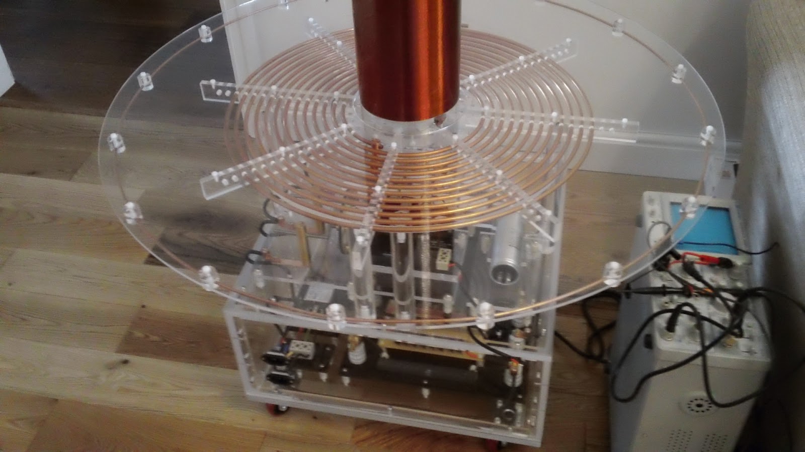
I've done a few more pics of the assembled tesla base as this is the first time all protective coatings and masking tape have been removed.
And finally a full length shot with the secondary and toroid back in place.

If you like this blog you can show your support by one or all of these. 1. +1 my blog and email it to a friend. 2. Follow me.... It's good to know someones interested. 3. Leave a comment.... All are appreciated.

Monday, 23 April 2012

Fitting the phase shift Transformer

Another rather productive day. On holiday at the moment so spent a few more hours on the Tesla build. Today I managed to get the step down tansformer mounted in the base of the phase shift module.
As you can see it mounts directly onto the base disc. If you remember the step down transformer was originally mounted on the second level of the Tesla base. The pic below shows its original position.
I removed the whole module including the perspex base. After separating the transformer from the base I used the old base to mark drill points onto the base disc of the phase shift module. After drilling these holes I fixed the transformer to the base disc using the original ceramic pillars.
This left a couple of jobs to finish up. Two M12 flex glands were fitted by drilling two 10.7mm clearance holes and tapping out to 12mm. I also drilled six 12mm holes in the top disc, these are purely for ventilation. There are 7 similar holes in the base around the transformer and as the base stands on small cork pads air should be able to circulate up through these holes and out the vent holes in the top.
I took a picture of the main power module and the phase shift module together just to show you how I have tried to design them with the same look.
Still have wiring to finish up and few other touches to the phase shift module but I think I have achieved a matching module.
Here's the module that replaces the repositioned step down module. It's a rather large 40microfarad capacitor and is part of the phase shift circuit.
The capacitor has a central M8 mounting bolt which screws into a vertical perspex 8mm thick square. This square is bolted to the perspex base and is reinforced by a secondary perspex square flush up against it and also bolted to the base.
Again, just a bit of wiring needed to finish off.

If you like this blog you can show your support by one or all of these. 1. +1 my blog and email it to a friend. 2. Follow me.... It's good to know someones interested. 3. Leave a comment.... All are appreciated.

Monday, 2 January 2012

Wiring in the Spark Gap

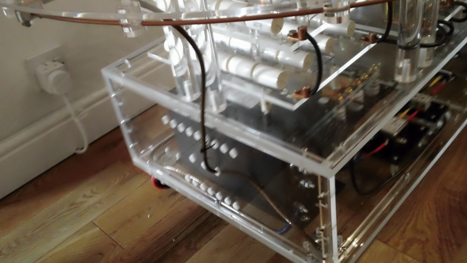
Had a spare hour today to do a bit of wiring on the tesla. I'm glad I put a bit of thought into the design of the main base unit as access will always be needed for tweaks and modifications. Access to the main base can be achieved by removing any of the side panels.
 For this job I removed the right hand side panel which gave me easy access to the safety gap end of the Terry filter. I needed to connect the left and right terminals to the left and right terminals on the synchronous spark gap module situated above on the next level.
I had previously drilled the 2 6mm holes for the passage of these wires from one level to the next so it was just a matter of making up the two wires and then threading them through.
The wire used is high quality GTO (Gas tube only) wire rated at 15,000V. This wire was sourced from Teslastuff.com and ordered from their eBay store. Click here if you want to take a look at the store.
I "sealed" the ends of the wires by coating in solder before fitting. This prevents repeated clamping from damaging the ends of the wires.
I tried to keep the wires reasonably short so they didn't pass to close to other components. This type of wire is almost all insulation but it won't do any harm to try to keep separation to a maximum.

Sunday, 4 September 2011

First layer plastic surgery

Spent a couple of hours in the garage drilling the various mounting holes in the base. 4 X 6mm holes for the neon transformer and 16 X 4mm holes for the Terry filter, the emf filter and the mains connector module.
Another 12 X 4mm holes were needed to mount the 10x10mm perspex square rod that runs around the perimeter of the base.
These 10x10mm perspex rods provide a means to screw the side panels onto the base.