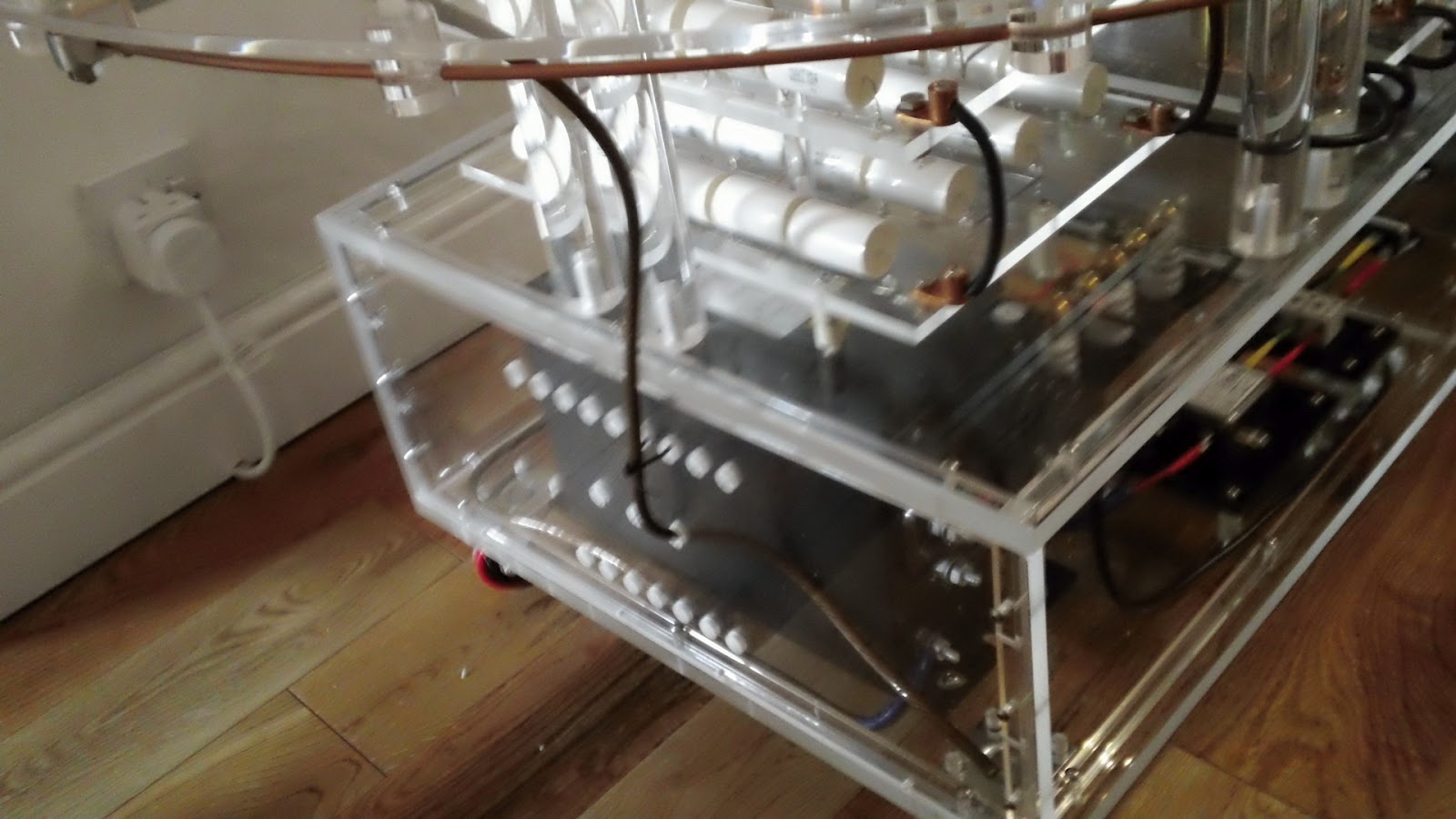
Today I decided to finish some of the electrical connections. Firstly I needed to complete some ground connections, 3 to be exact, and when I say ground I mean literally ground not mains earth ground. These are :-
1. Strike rail to ground.
2. Secondary coil to ground.
3. Neon transformer to ground.
I decided all 3 of the above will start from the ground post on the neon transformer as this has a large enough post to accomodate the multiple ring terminals.
You can see this terminal in the pic above, it's the lower terminal with the blue sheathed wire attached. In this pic I have removed the perspex side panel.
As the 3 grounds will exit the lower level perspex box I needed to drill 3 holes in the perspex side panel. I masked up the side panel so to protect the perspex and so I could mark my drill points. The welding wire for the grounds is 8mm in diameter but I decided to drill 12mm holes so the wires could pass through with the ring terminals attached. This would make assembly and maintenance much easier.
The left hole would house the secondary coil connection, the right the strike rail connection and the centre would be to the grounding spike. I marked the top on the masking tape mainly to show this side is the outside as the panels do fit better one way than the other. I drilled the three 12mm holes and then removed the masking tape. But unfortunately failed to note which side was marked top. So I took my best guess and offered up the panel and proceeded to refit the mounting bolts. Guess what?
Wrong way! the bolts did not line up correctly and the result is shown above. The perspex corner post cracked. The bolts did feel a little tight, I should have realised the panel was the wrong way round. Took me an extra hour to make the replacement post.
Here's the side panel and new corner post back in situ. Now to make up the wire lengths required for the two ground connections.
The first is the strike rail connection. The wire end at the strike rail fastened inside a copper lug so I impregnated the copper strands with solder to stop the wire end disintegrating due to repeated clamping. The other end terminates in a ring terminal which was also soldered.
Next I did the ground connection to the lower end of the secondary coil. Both ends of this wire were fitted with ring terminals, again soldered.
Above you can see the routing and end connections of these two ground wires.
I am not going to fit the wire to the ground spike yet, there's no point as it will just get in the way. It will pass through the central hole in the side panel and attach to the ground post of the neon transformer thus connecting the neon transformer, strike rail and secondary coil to ground. The ground spike will be situated in the middle of my back lawn. It will consist of a 4 foot copper rod driven fully into the ground. I will run the connecting wire under the turf across the lawn and out on to the patio.
If you like this blog you can show your support by one or all of these.
1. +1 my blog and email it to a friend.
2. Follow me.... It's good to know someones interested.
3. Leave a comment.... All are appreciated.
This is my blog of current hobbies, at the moment that happens to be all things Tesla so I have decided to build a Tesla coil and, as usual, I will go completely over the top with it.
Showing posts with label anti-strike rail. Show all posts
Sunday, 6 May 2012
Sunday, 1 January 2012
Clamp on strike rail earth connector
Today I fabricated a mock up clamp to earth the strike rail. I started with one of the copper electrical lugs that I bought from Teslastuff.com.
You will not find these listed anywhere on the website or on the Teslastuff eBay shop you will have to email the owner Alan and ask for a price. They are far better quality than anything I have found available in the UK. If you know different drop me an email. I used a length of aluminium 1/2" square rod to make the pieces that form the clamp.
These pieces started off as one block which I drilled with a 12mm bit to form the internal curve and a 6mm bit to form the bolt hole. I used a file to produce the curve on the other end. The block was then cut down the middle using a slotting saw on the milling machine. The two pieces were then clamped back together in a vice on the milling machine and then a 4mm hole drilled exactly on the interface of the two pieces. Using a perfectly flat surface and a piece of fine glass paper I worked the adjoining surfaces this makes the 4mm hole slightly smaller so it clamps tight on the 4mm strike rail.
Here are the assembled pieces. Straight away I spotted an improvement that could be made when fabricating the actual unit, if I put threads on the bolt hole on the top aluminium clamp plate I can dispense with the nut and use a shorter bolt. Also the actual unit will have copper clamping plates to reduce resistance (aluminium 2.7, copper 1.7ohm.m).
I will mount the finished clamp the other way up than shown above. There will be no need to move this clamp once it is in position on the strike rail. But, obviously, access to the grub screw will be needed to clamp the grounding wire.
With the improvements mentioned I think this clamp will do very nicely. Off to eBay to get some copper square rod.
You will not find these listed anywhere on the website or on the Teslastuff eBay shop you will have to email the owner Alan and ask for a price. They are far better quality than anything I have found available in the UK. If you know different drop me an email. I used a length of aluminium 1/2" square rod to make the pieces that form the clamp.
These pieces started off as one block which I drilled with a 12mm bit to form the internal curve and a 6mm bit to form the bolt hole. I used a file to produce the curve on the other end. The block was then cut down the middle using a slotting saw on the milling machine. The two pieces were then clamped back together in a vice on the milling machine and then a 4mm hole drilled exactly on the interface of the two pieces. Using a perfectly flat surface and a piece of fine glass paper I worked the adjoining surfaces this makes the 4mm hole slightly smaller so it clamps tight on the 4mm strike rail.
Here are the assembled pieces. Straight away I spotted an improvement that could be made when fabricating the actual unit, if I put threads on the bolt hole on the top aluminium clamp plate I can dispense with the nut and use a shorter bolt. Also the actual unit will have copper clamping plates to reduce resistance (aluminium 2.7, copper 1.7ohm.m).
I will mount the finished clamp the other way up than shown above. There will be no need to move this clamp once it is in position on the strike rail. But, obviously, access to the grub screw will be needed to clamp the grounding wire.
With the improvements mentioned I think this clamp will do very nicely. Off to eBay to get some copper square rod.
Labels:
anti-strike rail,
bobine de Tesla,
copper clamp,
Forming the primary coil,
make tesla coil,
nikola tesla,
paul walsh,
Strike rail,
strike rail for primary,
strike rail or not,
strike rail vs no strike rail,
strike tube,
tesla coil copper,
tesla coil strike rail
Saturday, 24 December 2011
Fitting the Primary Coil strike rail
With all the strike rail mounts finished and the strike rail formed into the approximate correct shape it was time to fit it all to the anti-strike disc. It was possible to loosely fit all the strike rail mounts and then thread the strike rail through each one.
I have used 15mm X M4 nylon bolts to secure the mounts may substitute these for stainless steel, still not decided.
Made a quick video just to give you a bit better view of the complete strike rail.
The rail is not a complete loop, it has a gap which is located inside one of the mounts. It needs this break to prevent induced eddy currents when the coil is running.
Here's a festive shot of the top of the tesla coil. Well it is Christmas!
I have used 15mm X M4 nylon bolts to secure the mounts may substitute these for stainless steel, still not decided.
Made a quick video just to give you a bit better view of the complete strike rail.
Here's a festive shot of the top of the tesla coil. Well it is Christmas!
Labels:
anti-strike disc,
anti-strike rail,
antistrike rail,
antistrike ring,
building the primary,
how to build a primary coil,
making a strike rail,
nikola tesla,
paul walsh,
Strike rail,
strike rail for primary,
strike rail or not,
strike rail vs no strike rail,
Tesla-Spule,
Тесла катушки
Friday, 23 December 2011
Finishing the strike rail mounts
Finished for the xmas break today and thought I would get the strike rail mounts finished off. I had already drilled a 3.3mm vertical hole in each one which would be tapped to accept a 4mm bolt to fasten to the anti-strike disc. Before tapping I needed to drill a horizontal hole through each mount through which the strike rail will pass. The strike rail is 4mm in diameter and as the rail is a large loop the holes in the mounts need to be slightly over 4mm to allow for the curve. I opted for 4.4mm and set up the milling machine for drilling.
I marked up the vice with masking tape so I could position each mount in the exact same place so I could lock the bed once the first mount is lined up for drilling.
All I needed to do is line up each mount with the masking tape as above and my holes will be in the same position on each one.
It was nice to be able to see the progress of the drill through the top of the mount. When approaching breaking through I greatly reduced pressure on the drill to prevent chipping the edges of the exit hole. This technique worked well, on inspection the exit holes were very neat. With the first mount drilled I checked that the 4.4mm hole would accept the curved 4mm strike rail. Bingo, 4.4mm is perfect.
After another 15 mounts the drilling was done. Now to tap the mount holes.
It's about now that I'm regretting the choice of using 16 mounts for the strike rail, 8 would have been plenty, keep telling myself it will look really good.
9 done, only another 7 to do. Didn't take quite as long as I thought as there's only about 10mm threads to cut in each one.
Here are the 16 mounts done and de-masked. They look fantastic.
I marked up the vice with masking tape so I could position each mount in the exact same place so I could lock the bed once the first mount is lined up for drilling.
All I needed to do is line up each mount with the masking tape as above and my holes will be in the same position on each one.
It was nice to be able to see the progress of the drill through the top of the mount. When approaching breaking through I greatly reduced pressure on the drill to prevent chipping the edges of the exit hole. This technique worked well, on inspection the exit holes were very neat. With the first mount drilled I checked that the 4.4mm hole would accept the curved 4mm strike rail. Bingo, 4.4mm is perfect.
After another 15 mounts the drilling was done. Now to tap the mount holes.
It's about now that I'm regretting the choice of using 16 mounts for the strike rail, 8 would have been plenty, keep telling myself it will look really good.
9 done, only another 7 to do. Didn't take quite as long as I thought as there's only about 10mm threads to cut in each one.
Here are the 16 mounts done and de-masked. They look fantastic.
Labels:
anti-strike disc,
anti-strike rail,
antistrike rail,
antistrike ring,
build a tesla,
building the primary,
designing the primary,
drilling the primary combs,
homemade tesla coil,
how to build a tesla coil,
making a strike rail,
paul walsh,
Strike rail,
strike rail material,
strike rail or not,
strike rail vs no strike rail,
strike tube
Sunday, 11 December 2011
Marking out and drilling mounts for the primary
Today I spent a few hours progressing with the primary coil. I needed to mark out the positioning of the 8 primary support combs. These will be attached to the underside of the large anti-strike disc by 3 nylon bolts per each comb. I had already masked up the anti-strike disc to protect it and to allow marking out, I marked up 8 "spokes" onto the disc by taping the disc down to our glass dining table and taping a 360° protractor into the centre cut-out.
The position of the 8 spokes could then be easily marked out using a long metal rule placed over the relevant degree markings and lined up with the dead centre.
Also mounted to the underside of the anti-strike disc will be 16 evenly space strike rail holders around the perimeter so I marked on another 8 spokes at 45° intervals between the primary coil combs. With all the spokes marked up I could decide on the nylon bolt positions and mark them out for later drilling.
Next job was to mark out the primary support combs. I don't want to "notch out" the combs as is the usual way to support the copper pipe of the primary. This method means you have to either glue or zip tie the tubing down, neither of which appealed to me. I plan to drill "full" holes into the combs and thread them onto the copper coil.
If you look at the coil plan above (or into my eyes, not around my eyes) you can see that the positions for the holes in each comb will be different. For my coil there is 8mm space between each rotation of the coil and the diameter of the copper tubing is 6.5mm so the holes in the combs need to be 14.5mm apart (centre to centre). This measurement is the same for each comb. As you move around to the next comb the spiral moves out by 14.5mm divided by 8 (1.8125) so there is an offset of 1.8125mm as you move around from comb to comb. You can avoid this complication by just moving the combs outwards by the same value when fixing them in place but I wanted all the combs to be the same distance from the secondary coil.
All the combs were masked up in the usual manner and then through carefully measuring my full scale primary plan I determined the position for the hole for the innermost coil on comb number 1. It was the easy to mark the position for the 1st hole in comb number 2 by adding 1.8125mm. And so on up to comb number 8. I didn't bother marking any subsequent holes onto the combs as I decided to fire up the digital vernier scales on my milling machine and locate them by just adding 14.5mm each time.
Not the best video but its really hard trying to film while drilling. Think I might invest ia a small tripod for my little Sony Bloggie.
I set up the milling machine so each perspex comb could be clamped in the the same place with an 10mm piece of pine stripwood underneath to prevent the drillbit chipping the back of the perspex as it breaks through. I positioned the bed so the drill bit was directly over the datum mark for the first hole. The hole was drilled and then the bed was moved 14.5mm to the left and the next hole drilled and so on.
I jotted down all the datum points as I drilled the first comb so I could use the info for the rest of the combs. And about 140 holes later......
Here's the drilled combs underneath the anti-strike disc. I have drilled all the necessary pilot holes in the strike disc, this will make it very easy to mark up the 3 bolt holes onto each comb by simply sticking a pencil through the pilot holes in the anti-strike disc.
I set up the milling machine so each perspex comb could be clamped in the the same place with an 10mm piece of pine stripwood underneath to prevent the drillbit chipping the back of the perspex as it breaks through. I positioned the bed so the drill bit was directly over the datum mark for the first hole. The hole was drilled and then the bed was moved 14.5mm to the left and the next hole drilled and so on.
I jotted down all the datum points as I drilled the first comb so I could use the info for the rest of the combs. And about 140 holes later......
Here's the drilled combs underneath the anti-strike disc. I have drilled all the necessary pilot holes in the strike disc, this will make it very easy to mark up the 3 bolt holes onto each comb by simply sticking a pencil through the pilot holes in the anti-strike disc.
Labels:
anti-strike disc,
anti-strike rail,
antistrike rail,
antistrike ring,
best tesla coil,
building the primary,
designing the primary,
drilling the primary combs,
how to build a primary coil,
joining perspex,
paul walsh,
primary support combs,
trent plastics
Subscribe to:
Posts (Atom)