Showing posts with label grounding rod. Show all posts

Friday, 9 August 2013

More "Ground" Work on the Tesla Coil

Hi again. Over the last couple of days I have been working on the grounding system for my Tesla. As mentioned in my last post, I had already sank one copper rod in the lawn. Plan was to get another couple of rods form B+Q and have 3 ground points spread across the lawn. Slight problem, I sank the first rod several weeks back and I now can't find it!
So 3 rods were purchased from my local B+Q. The rods are about £12 each, they are 1m long 10mm diameter copper plated rod with a nice copper terminal clamp.
The 3 grounding wires will pass through the conservatory wall and meet in the pattress box. They will pass through 3 separate holes drilled with a super long 8mm masonry bit.
I removed a small piece of turf (about 18" square) and dug out some earth down to about 10". Here's a picture of the first hole. The wire will be sank under the turf by cutting a line with a spade and easing the turf up and pushing the wire under (a trick learned watching Virgin installation engineers).

If you like this blog you can show your support by one or all of these. 1. +1 my blog and email it to a friend. 2. Follow me.... It's good to know someones interested. 3. Leave a comment.... All are appreciated.
The copper plated rod was hammered into the centre of the hole. You have to fit the clamp onto the rod before you sink it as the hammering will splay out the top of the rod making it impossible to slide the clamp over afterwards. The grounding wire was attached using a solder ring terminal and the hole back filled and turf replaced.
Above you can see the position of the second ground wire. The process was repeated exactly the same as the first ground point.
And here is the 3rd and final ground wire laid out. All the wires run into the gravel filled trench that runs around the conservatory wall. You can see Karel (wife) covering the two completed grounds.
Here's the last rod being sank. Think I was pretty lucky that all the rods went in without to much trouble.
Here are all the 3 wires in place. Next job is to wire up the grounding plate in the conservatory wall.

If you like this blog you can show your support by one or all of these. 1. +1 my blog and email it to a friend. 2. Follow me.... It's good to know someones interested. 3. Leave a comment.... All are appreciated.

Sunday, 13 May 2012

Tesla Coil Extras

Well it was nearly finished.... I am sure I will keep on posting extra additions and also experiences of my first fire-ups and tunings. First addition was mentioned in my last post, the safety bleed resistor for the large 40uF capacitor in the SSG circuit. This was quite a quick fit, the resistor is only small so I decided to fit it on the side of the module that held the 40uF capacitor. I made 2 identical mounting posts out of 10mm diameter brass rod. The posts are 25mm long and the resistor sits in 3mm diameter horizontal holes 12.5mm up each post.
The resistor legs are clamped by M3 grub screws at 90deg to the mounting holes. Electrical connection to the capacitor are ring terminals onto M4 allen key bolts (stainless of course) into the tops of the mounting posts.
I made up the wires to the resistor starting with female 1/4" piggyback blade connectors which meant I didn't have to amend the existing wires to the SSG, they could just plug into the piggybacks.
While the weather was good I decided to sink the grounding rod in the middle of my back lawn. The rod is 1 metre long and I thought it would take several attempts to sink it as the garden seems to have a thick layer of industrial rubble just under the surface. Must have been my lucky day as I hammered the rod well below the surface on the first attempt. I removed a small square of turf before I started. You can just see the refitted turf in the above pic. Next dry weekend I will run the earth lead from the rod under the lawn turf to the patio.

If you like this blog you can show your support by one or all of these. 1. +1 my blog and email it to a friend. 2. Follow me.... It's good to know someones interested. 3. Leave a comment.... All are appreciated.

Sunday, 6 May 2012

Tesla coil ground connections

Today I decided to finish some of the electrical connections. Firstly I needed to complete some ground connections, 3 to be exact, and when I say ground I mean literally ground not mains earth ground. These are :-

1. Strike rail to ground.
2. Secondary coil to ground.
3. Neon transformer to ground.

I decided all 3 of the above will start from the ground post on the neon transformer as this has a large enough post to accomodate the multiple ring terminals.
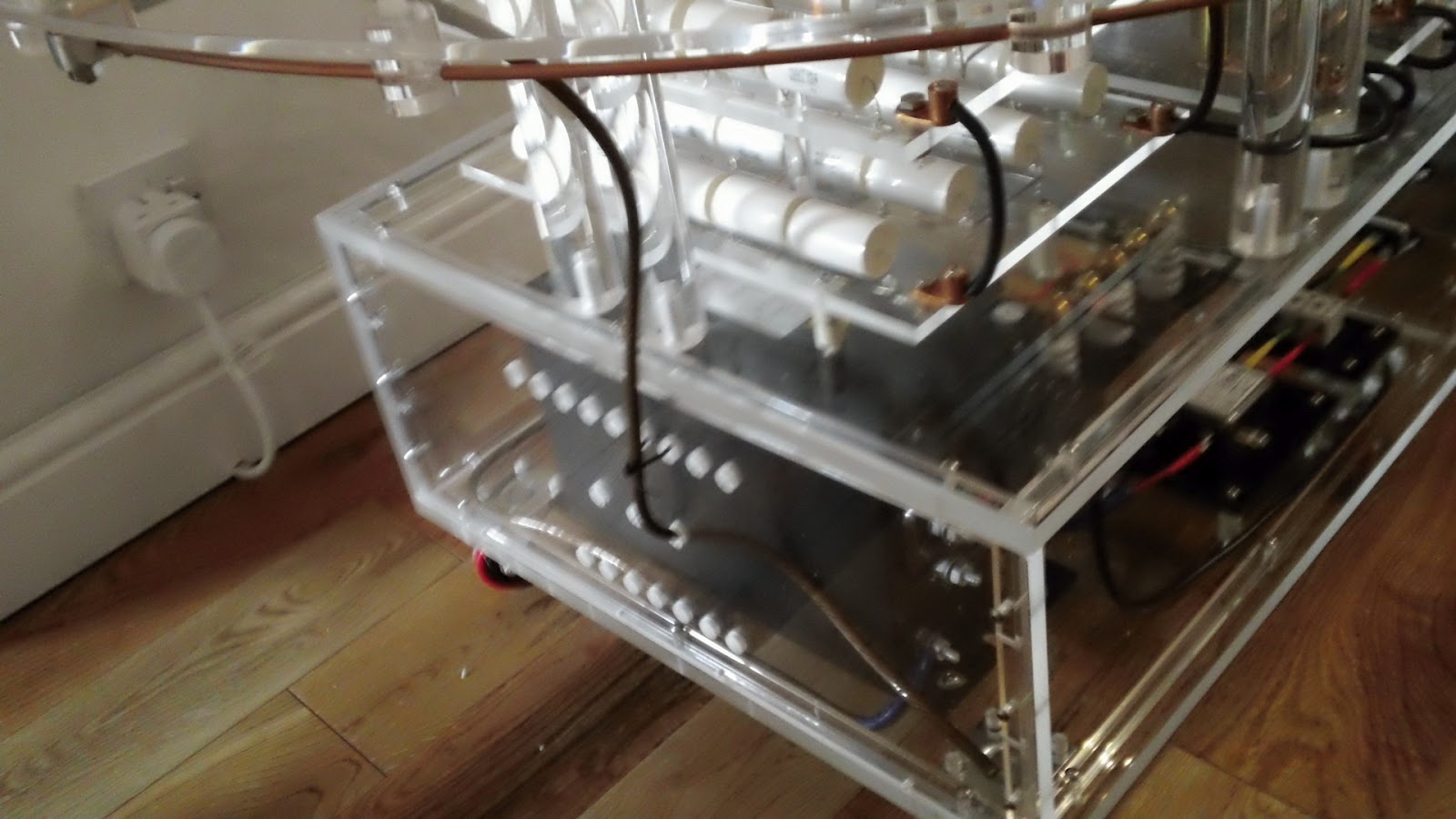
You can see this terminal in the pic above, it's the lower terminal with the blue sheathed wire attached. In this pic I have removed the perspex side panel.
As the 3 grounds will exit the lower level perspex box I needed to drill 3 holes in the perspex side panel. I masked up the side panel so to protect the perspex and so I could mark my drill points. The welding wire for the grounds is 8mm in diameter but I decided to drill 12mm holes so the wires could pass through with the ring terminals attached. This would make assembly and maintenance much easier.
The left hole would house the secondary coil connection, the right the strike rail connection and the centre would be to the grounding spike. I marked the top on the masking tape mainly to show this side is the outside as the panels do fit better one way than the other. I drilled the three 12mm holes and then removed the masking tape. But unfortunately failed to note which side was marked top. So I took my best guess and offered up the panel and proceeded to refit the mounting bolts. Guess what?
Wrong way! the bolts did not line up correctly and the result is shown above. The perspex corner post cracked. The bolts did feel a little tight, I should have realised the panel was the wrong way round. Took me an extra hour to make the replacement post.
Here's the side panel and new corner post back in situ. Now to make up the wire lengths required for the two ground connections.
The first is the strike rail connection. The wire end at the strike rail fastened inside a copper lug so I impregnated the copper strands with solder to stop the wire end disintegrating due to repeated clamping. The other end terminates in a ring terminal which was also soldered.
Next I did the ground connection to the lower end of the secondary coil. Both ends of this wire were fitted with ring terminals, again soldered.
Above you can see the routing and end connections of these two ground wires.
I am not going to fit the wire to the ground spike yet, there's no point as it will just get in the way. It will pass through the central hole in the side panel and attach to the ground post of the neon transformer thus connecting the neon transformer, strike rail and secondary coil to ground. The ground spike will be situated in the middle of my back lawn. It will consist of a 4 foot copper rod driven fully into the ground. I will run the connecting wire under the turf across the lawn and out on to the patio.

If you like this blog you can show your support by one or all of these. 1. +1 my blog and email it to a friend. 2. Follow me.... It's good to know someones interested. 3. Leave a comment.... All are appreciated.