I have started work on the new toroid mounting system which differs in design from the method used on the first secondary coil. This time electrical connection to the toroid from the top of the secondary coil will not pass inside the coil form but will gently spiral around the mount and then finish as a copper disc which will be in direct contact with the underside of the toroid. The final system incorporates good secondary coil design taken from Stefan's Tesla Pages and the fast easy assembly of my first design.
Above is a quick sketch showing the basics of the new mount. Here we see 3 acrylic disc which are 107mm in diameter and 15mm thick. The middle disc has an central 25mm hole. All bolts are nylon with the center bolt being M8 and the four others are M6. The diagram only shows the 2 side M6 bolts, there are another 2 front and rear. The bottom disc will be Tensoled to the top cap of the secondary coil and the four holes will be threaded to take the M6 bolts. The middle and top disc corresponding holes will be 6mm clearance holes with the top disc holes being countersunk. The central hole in the top disc will be threaded M8. The copper electrode disc will sit on top of the uppermost disc (probably bonded to it) and the the toroid mounts over the M8 bolt sandwiching the copper plate. The copper plate is soldered to the copper tail of the secondary with the tail gently spiralling (with some excess) around the toroid mount. This system will allow extra acrylic discs to be fitted to adjust the spacing between the toroid and the secondary coil.
I ordered four discs from Trent Plastics. The 3 required for the construction of the mount plus an extra to be inserted as a spacer. All the discs were the same apart from the one with the 25mm central cut-out. Above you can see the top 3 discs including the extra spacer. The lefthand disc has just been drilled to form the four 6mm clearance holes and the central hole which will be threaded to M8.
I the stacked the drilled disc on top of the other 2 and taped them tightly together. This allowed me to use the existing 6mm holes in the top disc as a template to drill 6mm clearance holes through the other 2 discs. After this was done I the added the fourth disc to the botton of the stack of disc, again taping it tightly to the others. I then passed the 6mm drill down each hole with just enough pressure to mark the center of the drill bit on the bottom disc. The stack was then separated and I could use the drill dimples on the surface of the bottom disc to centre the 5mm drill bit before drilling.
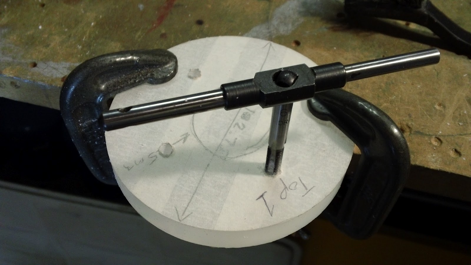
Here I am taping the four 5mm holes in the bottom acrylic disc to accept the M6 nylon bolts. Remember, this is the disc that will be bonded to the top cap of the secondary.
After removing all the protective masking tape I did a quick trial assembly just to make sure everything lined up OK.
And here's the mount in situ, not bonded yet, that will have to wait till the secondary is wound. That's the next job.
If you like this blog you can show your support by one or all of these.
1. +1 my blog and email it to a friend.
2. Follow me.... It's good to know someones interested.
3. Leave a comment.... All are appreciated.
This is my blog of current hobbies, at the moment that happens to be all things Tesla so I have decided to build a Tesla coil and, as usual, I will go completely over the top with it.
Showing posts with label attaching the toroid. Show all posts
Monday, 18 June 2012
Thursday, 8 December 2011
Attaching the Toroid to the Secondary Coil
I have been considering how to attach the toroid to the secondary coil. This involves a physical connection to hold a rather expensive gorgeous hand spun aluminium toroid and an electrical connection between the toroid and the secondary coil. I would like to be able to quickly remove the toroid for transport and access purposes but without risking damage to any electrical connections. I have come to the conclusion that the secondary coil should have a permanent threaded conducting protrusion on its top cap which is electrically connected to the secondary coil. The toroid simply slots over this protrusion and is secured by a threaded knob.
Here's the top of the secondary, the central hole is 10mm and was drilled originally to mount the secondary coil onto the winding jig shaft (a 10mm threaded rod). I thought 10mm was a little excessive as a mount for the toroid so decided to bush the hole down to 8mm with a piece of brass rod.
I turned a flange on one side of the insert. This would sit on the under side of the secondary top cap.
Here's the bush fitted, admittedly the wrong way, just making sure it was a snug fit.
Ok, so I now have the top cap ready to accept some kind of 8mm bolt that will protrude upwards. I need to do 2 more things. Firstly, I want to add a little height to the top of the secondary to lift the toroid, secondly, I need to make this protruding bolt captive so when I undo the fastening for the toroid this bolt doesnt spin or release and drop down the inside of the secondary. To cover off both these requirements I am going to use two pieces of perspex. The first is a 100mm diameter 15mm thick clear disc ordered from my favourite plastic supplier Trent Plastics.
As you can see I have masked the disc up and drilled a central 8mm hole. This disc will sit on top of the secondary coil top cap. The second piece of perspex required is exactly the same size except it has a 25mm central cut-out.
These two discs will be bonded together as shown in the mock up below.
The larger hole in the top disc will provide clearance for the nut which will make the toroid mounting pin captive. OK, now for the mounting pin.
I cut a length of 16mm diameter copper rod, started off with about 10cm. The shank of the pin needed to be 65mm long and 8mm in diameter.
Turning the copper rod down to 8mm was down using a type 5 parting tool. Probably not the best tool to use but I always have the most success with this type. The material was removed in 0.4mm passes, I didn't want to risk any deeper cuts as it's quite a long shaft to turn and copper is pretty soft. I had an experience in the past where the tool dug in and the work was completely destroyed.
The toroid will be secured in place with an M8 threaded knob so I needed to cut some threads into the pin. There's quite a lot of info on the web about cutting threads onto copper rods, lots of comments about poor results and differing views on cutting methods and lubricants. I used plenty of WD-40 and patience. Don't try to cut too much thread in one go, I found it best to cut 1/8 of a turn each time and reverse the die 1/4 turn back every time. Use plenty of lube and clear swarf from the die when needed.
Here's the assembled mounting pin.
The copper lug will provide electrical connection to the secondary coil. The nylon M8 nut in the top pic will be replaced with a stainless steel version.
Subscribe to:
Posts (Atom)