Showing posts with label building a winding jig. Show all posts

Monday, 18 June 2012

New Toroid mount System

I have started work on the new toroid mounting system which differs in design from the method used on the first secondary coil. This time electrical connection to the toroid from the top of the secondary coil will not pass inside the coil form but will gently spiral around the mount and then finish as a copper disc which will be in direct contact with the underside of the toroid. The final system incorporates good secondary coil design taken from Stefan's Tesla Pages and the fast easy assembly of my first design.
Above is a quick sketch showing the basics of the new mount. Here we see 3 acrylic disc which are 107mm in diameter and 15mm  thick. The middle disc has an central 25mm hole. All bolts are nylon with the center bolt being M8 and the four others are M6. The diagram only shows the 2 side M6 bolts, there are another 2 front and rear. The bottom disc will be Tensoled to the top cap of the secondary coil and the four holes will be threaded to take the M6 bolts. The middle and top disc corresponding holes will be 6mm clearance holes with the top disc holes being countersunk. The central hole in the top disc will be threaded M8. The copper electrode disc will sit on top of the uppermost disc (probably bonded to it) and the the toroid mounts over the M8 bolt sandwiching the copper plate. The copper plate is soldered to the copper tail of the secondary with the tail gently spiralling (with some excess) around the toroid mount. This system will allow extra acrylic discs to be fitted to adjust the spacing between the toroid and the secondary coil.
I ordered four discs from Trent Plastics. The 3 required for the construction of the mount plus an extra to be inserted as a spacer. All the discs were the same apart from the one with the 25mm central cut-out. Above you can see the top 3 discs including the extra spacer. The lefthand disc has just been drilled to form the four 6mm clearance holes and the central hole which will be threaded to M8.
I the stacked the drilled disc on top of the other 2 and taped them tightly together. This allowed me to use the existing 6mm holes in the top disc as a template to drill 6mm clearance holes through the other 2 discs. After this was done I the added the fourth disc to the botton of the stack of disc, again taping it tightly to the others. I then passed the 6mm drill down each hole with just enough pressure to mark the center of the drill bit on the bottom disc. The stack was then separated and I could use the drill dimples on the surface of the bottom disc to centre the 5mm drill bit before drilling.
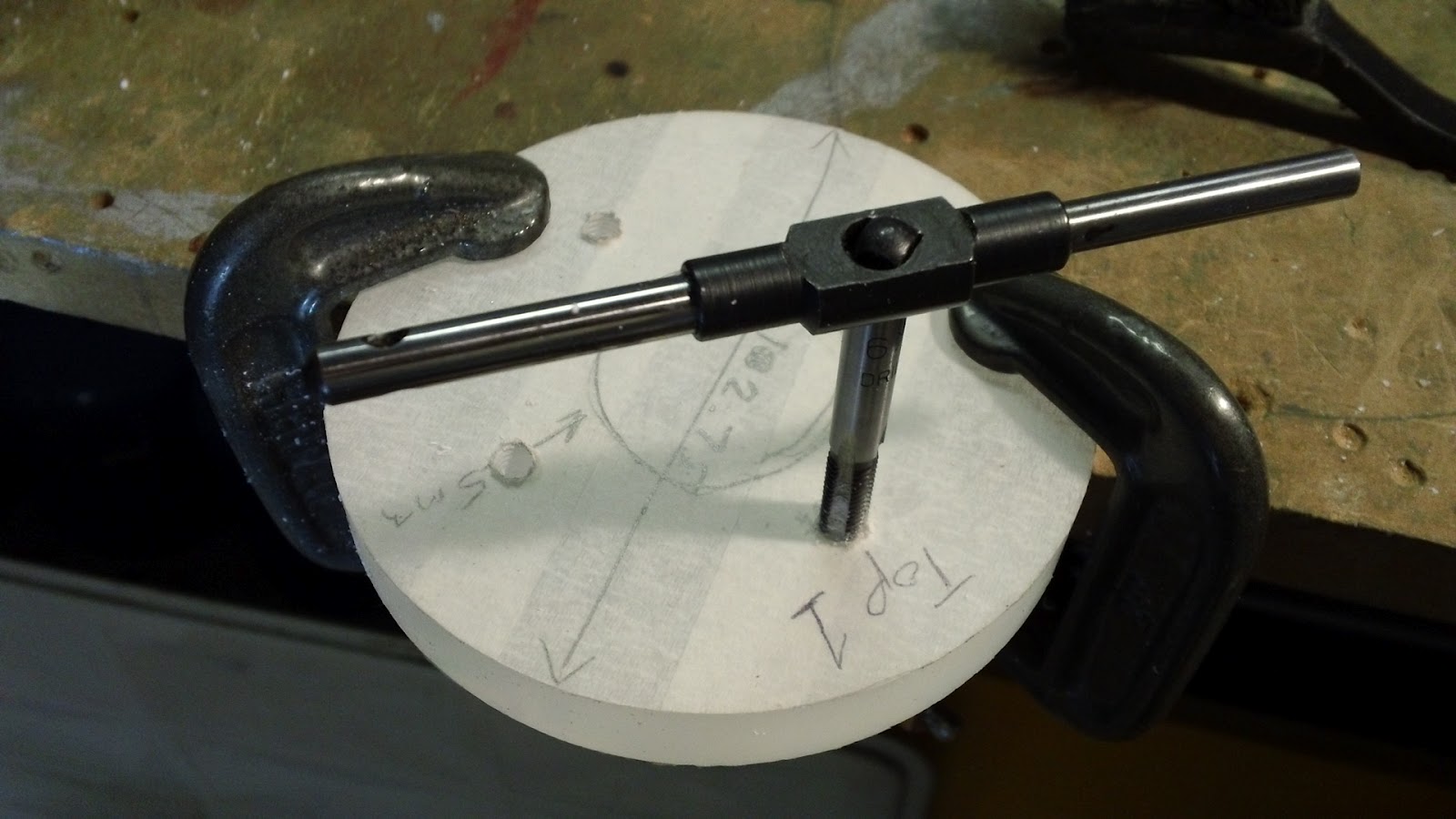
Here I am taping the four 5mm holes in the bottom acrylic disc to accept the M6 nylon bolts. Remember, this is the disc that will be bonded to the top cap of the secondary.
After removing all the protective masking tape I did a quick trial assembly just to make sure everything lined up OK.
And here's the mount in situ, not bonded yet, that will have to wait till the secondary is wound. That's the next job.

If you like this blog you can show your support by one or all of these. 1. +1 my blog and email it to a friend. 2. Follow me.... It's good to know someones interested. 3. Leave a comment.... All are appreciated.

Sunday, 9 October 2011

Winding Jig Upgrades

I finished the secondary coil winding jig a few weeks back and was planning to wind the coil by spinning the perspex tube by hand. After deciding to upgrade to a 6" coil and reading lots more winding stories on the web I have decided to upgrade my jig by adding a motor.
The picture above shows the finished winding jig in its manual mode to speak. The easiest way to rotate the secondary coil would be to drive it directly with a rubber drive belt otherwise I would have to drive the central shaft and fix the perspex former to it. Direct drive to the coil tube via rubber belt was chosen and the parts quest was on.
    I would need a motor with a suitable gearbox, a pulley to fit the output shaft and a rubber drive belt. First place I tried was Maplin, I had bought a similar motor from there in the passed to power the belt on a Van der Graaf generator I made. They had the motor I needed but not the belt or a suitable pulley so I carried on looking. I found everything I needed at Technobots they had an excellent choice of motors, pulleys and drive belts, they took Paypal and delivered the stuff within a few days. I was aiming for  a coil rotational speed of around 15rpm so a bit of maths was needed to work out gearbox ratio, pulley size and drive belt diameter. Final positioning of the motor on the jig is really by trial and error, you just need to get the right tension on the drive belt so it doesn't slip as you are winding. I had to mount the motor on a small piece of wood to get the correct spacing.
The motor I used was a 540 size motor that came with a 148:1 reduction gearbox. The mounting plate comes with it, the output shaft is 6mm and it can be run on 4.5v to 15v.
I needed to make a small cut out on the back panel of the jig to allow clearance for the drive belt. The upgrade was finished and it went quite well to say that I hadn't designed the jig to take a motor to start with.
I also knocked together a spool support for the 26awg wire. This would need to allow the feed spool to rotate freely so I did my typical over engineering on it. Starting with an old piece of wood and a length of 10mm aluminium rod.
I had a sealed bearing with a 10mm ID to hand so I turned a 10mm ID X 16mm OD 3mm spacer which went onto the 10mm vertical aluminium shaft followed by the bearing.
Then another 10mm ID X 16mm OD spacer, this time 15mm deep.
Then the spool itself then another spacer/bush to keep the top of the spool centred. Doesn't look pretty but works very nicely.

Saturday, 1 October 2011

Secondary top finished

Have just completed the top end disc for the secondary coil. It's pretty much a carbon copy of the base disc but obviously doesn't require the extra holes for mounting to the base.
As well as the 8 4mm holes around the circumference there is also a central 10mm diameter hole which serves two purposes. Firstly, it allows the top-load to be electrically connected to the coil on the secondary. Secondly, in conjunction with the same hole in the base disc, it allows the whole secondary coil assembly to be mounted on the 10mm shaft of my coil winding jig.
The next job is to wind the coil. This will be the first time winding such a large coil but hopefully should go OK.

Monday, 12 September 2011

Secondary Coil Winding Jig

After reading lots of tesla build diaries and after visiting many HV websites I have realised the only way to create a nice secondary coil is by winding it on some kind of jig. One of the favourite ways is to use a lathe and if the lathe is not long enough to create an "extended" tailstock. Unfortunately my lathe is nowhere near big enough as the chuck is only around 80cm and there's just not enough clearance to spin a length of 110mm (4") pipe. So I have decided to build a jig, but to keep it simple, it will be human powered (son Damien to be exact) and will be big enough to wind up to 6" diameter coils, just in case I want to upgrade from 4" in the future.

   One visit to B+Q later. I have

Pack of 2 lengths of 1800mm by 144mm by 20.5mm planed pine.
1 metre length of 10mm threaded bar.
1 metre length of 12mm OD 10mm ID steel tube.
Small bag of 40mm wood screws.
4 10mm plain nuts.
Wood glue.

While at B+Q I got the wood cut to the lengths needed for construction. The cutting service was free and meant all cuts where perfectly square.
The above pic shows the finished article. The base and the backboard are both 900mm long and are glued and screwed along the adjoining edge. The end plates are made by gluing and screwing 2 pieces of 144mm by 144mm by 20.5mm together. The end plates can then be stacked together and drilled at the same time. The hole needs to be 12mm. I then cut 2 40mm lengths of 12mm tube and hammered one into each hole in the end plates. This creates a neat metal bush in each of the wooden end plates. The two end plates were then screwed to the back and base board. I didn't glue them so they can be repositioned if needed.
Here's a closer view of one of the end plates. Doubling up and using 2 pieces of wood provides a bigger bearing for the shaft and also adds extra strength. The 12mm holes are offset to front and top of the end plates. This provides clearance from the base and back board to accomodate a 6" diameter pipe.
Not easy to see, but there is a neat little bush in there which should stop the threads chomping away at the hole.