I have started work on the new toroid mounting system which differs in design from the method used on the first secondary coil. This time electrical connection to the toroid from the top of the secondary coil will not pass inside the coil form but will gently spiral around the mount and then finish as a copper disc which will be in direct contact with the underside of the toroid. The final system incorporates good secondary coil design taken from Stefan's Tesla Pages and the fast easy assembly of my first design.
Above is a quick sketch showing the basics of the new mount. Here we see 3 acrylic disc which are 107mm in diameter and 15mm thick. The middle disc has an central 25mm hole. All bolts are nylon with the center bolt being M8 and the four others are M6. The diagram only shows the 2 side M6 bolts, there are another 2 front and rear. The bottom disc will be Tensoled to the top cap of the secondary coil and the four holes will be threaded to take the M6 bolts. The middle and top disc corresponding holes will be 6mm clearance holes with the top disc holes being countersunk. The central hole in the top disc will be threaded M8. The copper electrode disc will sit on top of the uppermost disc (probably bonded to it) and the the toroid mounts over the M8 bolt sandwiching the copper plate. The copper plate is soldered to the copper tail of the secondary with the tail gently spiralling (with some excess) around the toroid mount. This system will allow extra acrylic discs to be fitted to adjust the spacing between the toroid and the secondary coil.
I ordered four discs from Trent Plastics. The 3 required for the construction of the mount plus an extra to be inserted as a spacer. All the discs were the same apart from the one with the 25mm central cut-out. Above you can see the top 3 discs including the extra spacer. The lefthand disc has just been drilled to form the four 6mm clearance holes and the central hole which will be threaded to M8.
I the stacked the drilled disc on top of the other 2 and taped them tightly together. This allowed me to use the existing 6mm holes in the top disc as a template to drill 6mm clearance holes through the other 2 discs. After this was done I the added the fourth disc to the botton of the stack of disc, again taping it tightly to the others. I then passed the 6mm drill down each hole with just enough pressure to mark the center of the drill bit on the bottom disc. The stack was then separated and I could use the drill dimples on the surface of the bottom disc to centre the 5mm drill bit before drilling.
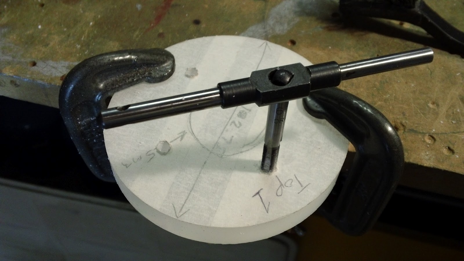
Here I am taping the four 5mm holes in the bottom acrylic disc to accept the M6 nylon bolts. Remember, this is the disc that will be bonded to the top cap of the secondary.
After removing all the protective masking tape I did a quick trial assembly just to make sure everything lined up OK.
And here's the mount in situ, not bonded yet, that will have to wait till the secondary is wound. That's the next job.
If you like this blog you can show your support by one or all of these.
1. +1 my blog and email it to a friend.
2. Follow me.... It's good to know someones interested.
3. Leave a comment.... All are appreciated.
This is my blog of current hobbies, at the moment that happens to be all things Tesla so I have decided to build a Tesla coil and, as usual, I will go completely over the top with it.
Showing posts with label drilling acrylic. Show all posts
Monday, 18 June 2012
Sunday, 17 June 2012
Making the Second Tesla Secondary Coil
Well here we go with the build of the replacement secondary coil. Rather than jump straight in and build an identical secondary with thicker gauge wire and hence less turns I decided to do a little more homework on secondary coil designs. One thing had always concerned me with the design of the first secondary I built. This was the termination of the ends of the coil inside the secondary form. The top and bottom copper tails pass through small holes drilled in the wall of the secondary form and make electrical connection through the top and bottom end caps.
The pic above shows the top electrical connection on the old secondary coil. You can see the copper tail clamped into the lug underneath the perspex cap. A very neat set-up but nearly every knowledgeable Tesla site I have seen strongly advises against this. The only one who seems to prefer this method is Alan at teslastuff.com who has had great success with this design. My final decision on the design of the new coil was strongly influenced by a page at www.capturedlightning.org. Stefan really seems to know his stuff when it comes to design and build of secondary coils so I decided to proceed using many of his recommendations.
The overall length and diameter of the new coil form was the same and again it would be made from 150mm diameter 3mm thick clear acrylic tubing with top and bottom caps in 15mm thick clear acrylic. The new secondary will mount to the existing 8 mount holes in the tesla base unit so the secondary base cap is an exact copy of the original. If you want to see the original post showing construction of this you can find it here.
The pic above shows the new secondary coil form with the top and bottom caps in place.
Here is a close-up of the bottom cap of the secondary showing the 8 nylon bolts that pass through mounting holes in the primary coil support disc. The central hole is 10mm in dameter and will only be used to thread the whole form onto my winding jig. After winding the hole will be permanently sealed by a turned acrylic peg turned (very successfully) on my lathe.
The peg is a really close fit and the flat area will provide a good surface to be bonded with Tensol 12.
Above you can see a trail fit of the peg. Obviously it will be fitted on top of the base cap. The coil form is now ready to wound on the winding jig. However, not tonight, time for a quick spin in the new RCZ. Spot the new wheels.
If you like this blog you can show your support by one or all of these. 1. +1 my blog and email it to a friend. 2. Follow me.... It's good to know someones interested. 3. Leave a comment.... All are appreciated.
The pic above shows the top electrical connection on the old secondary coil. You can see the copper tail clamped into the lug underneath the perspex cap. A very neat set-up but nearly every knowledgeable Tesla site I have seen strongly advises against this. The only one who seems to prefer this method is Alan at teslastuff.com who has had great success with this design. My final decision on the design of the new coil was strongly influenced by a page at www.capturedlightning.org. Stefan really seems to know his stuff when it comes to design and build of secondary coils so I decided to proceed using many of his recommendations.
The overall length and diameter of the new coil form was the same and again it would be made from 150mm diameter 3mm thick clear acrylic tubing with top and bottom caps in 15mm thick clear acrylic. The new secondary will mount to the existing 8 mount holes in the tesla base unit so the secondary base cap is an exact copy of the original. If you want to see the original post showing construction of this you can find it here.
The pic above shows the new secondary coil form with the top and bottom caps in place.
Here is a close-up of the bottom cap of the secondary showing the 8 nylon bolts that pass through mounting holes in the primary coil support disc. The central hole is 10mm in dameter and will only be used to thread the whole form onto my winding jig. After winding the hole will be permanently sealed by a turned acrylic peg turned (very successfully) on my lathe.
The peg is a really close fit and the flat area will provide a good surface to be bonded with Tensol 12.
Above you can see a trail fit of the peg. Obviously it will be fitted on top of the base cap. The coil form is now ready to wound on the winding jig. However, not tonight, time for a quick spin in the new RCZ. Spot the new wheels.
If you like this blog you can show your support by one or all of these. 1. +1 my blog and email it to a friend. 2. Follow me.... It's good to know someones interested. 3. Leave a comment.... All are appreciated.
Monday, 23 April 2012
Fitting the phase shift Transformer
Another rather productive day. On holiday at the moment so spent a few more hours on the Tesla build. Today I managed to get the step down tansformer mounted in the base of the phase shift module.
As you can see it mounts directly onto the base disc. If you remember the step down transformer was originally mounted on the second level of the Tesla base. The pic below shows its original position.
I removed the whole module including the perspex base. After separating the transformer from the base I used the old base to mark drill points onto the base disc of the phase shift module. After drilling these holes I fixed the transformer to the base disc using the original ceramic pillars.
This left a couple of jobs to finish up. Two M12 flex glands were fitted by drilling two 10.7mm clearance holes and tapping out to 12mm. I also drilled six 12mm holes in the top disc, these are purely for ventilation. There are 7 similar holes in the base around the transformer and as the base stands on small cork pads air should be able to circulate up through these holes and out the vent holes in the top.
I took a picture of the main power module and the phase shift module together just to show you how I have tried to design them with the same look.
Still have wiring to finish up and few other touches to the phase shift module but I think I have achieved a matching module.
Here's the module that replaces the repositioned step down module. It's a rather large 40microfarad capacitor and is part of the phase shift circuit.
The capacitor has a central M8 mounting bolt which screws into a vertical perspex 8mm thick square. This square is bolted to the perspex base and is reinforced by a secondary perspex square flush up against it and also bolted to the base.
Again, just a bit of wiring needed to finish off.
If you like this blog you can show your support by one or all of these. 1. +1 my blog and email it to a friend. 2. Follow me.... It's good to know someones interested. 3. Leave a comment.... All are appreciated.
As you can see it mounts directly onto the base disc. If you remember the step down transformer was originally mounted on the second level of the Tesla base. The pic below shows its original position.
I removed the whole module including the perspex base. After separating the transformer from the base I used the old base to mark drill points onto the base disc of the phase shift module. After drilling these holes I fixed the transformer to the base disc using the original ceramic pillars.
This left a couple of jobs to finish up. Two M12 flex glands were fitted by drilling two 10.7mm clearance holes and tapping out to 12mm. I also drilled six 12mm holes in the top disc, these are purely for ventilation. There are 7 similar holes in the base around the transformer and as the base stands on small cork pads air should be able to circulate up through these holes and out the vent holes in the top.
I took a picture of the main power module and the phase shift module together just to show you how I have tried to design them with the same look.
Still have wiring to finish up and few other touches to the phase shift module but I think I have achieved a matching module.
Here's the module that replaces the repositioned step down module. It's a rather large 40microfarad capacitor and is part of the phase shift circuit.
The capacitor has a central M8 mounting bolt which screws into a vertical perspex 8mm thick square. This square is bolted to the perspex base and is reinforced by a secondary perspex square flush up against it and also bolted to the base.
Again, just a bit of wiring needed to finish off.
If you like this blog you can show your support by one or all of these. 1. +1 my blog and email it to a friend. 2. Follow me.... It's good to know someones interested. 3. Leave a comment.... All are appreciated.
Labels:
auto transformer,
best variac,
build a tesla,
changing ac phase,
drilling acrylic,
drilling perspex,
homemade tesla coil,
how to build a primary coil,
terry filter
Location:
Radcliffe M26 3TG, UK
Saturday, 1 October 2011
Secondary top finished
Have just completed the top end disc for the secondary coil. It's pretty much a carbon copy of the base disc but obviously doesn't require the extra holes for mounting to the base.
As well as the 8 4mm holes around the circumference there is also a central 10mm diameter hole which serves two purposes. Firstly, it allows the top-load to be electrically connected to the coil on the secondary. Secondly, in conjunction with the same hole in the base disc, it allows the whole secondary coil assembly to be mounted on the 10mm shaft of my coil winding jig.
The next job is to wind the coil. This will be the first time winding such a large coil but hopefully should go OK.
As well as the 8 4mm holes around the circumference there is also a central 10mm diameter hole which serves two purposes. Firstly, it allows the top-load to be electrically connected to the coil on the secondary. Secondly, in conjunction with the same hole in the base disc, it allows the whole secondary coil assembly to be mounted on the 10mm shaft of my coil winding jig.
The next job is to wind the coil. This will be the first time winding such a large coil but hopefully should go OK.
Friday, 30 September 2011
Secondary base finished
Just got in from the garage. Spent a couple of hours drilling and tapping the holes in the secondary coil and the bottom disc.
The eight holes around the perimeter are tapped to accept 20mm M4 bolts which will pass through corresponding 4mm holes in the secondary coil. The other eight holes started as 7mm plain holes and were then tapped to M8. They will be used to bolt the secondary coil down to the base.
The holes were drilled with the disc in situ inside the secondary coil. The drill size required is 3.3mm. After drilling the components were separated and the disc tapped to M4. The 3.3mm holes in the secondary were opened up to 4mm.
Here you can see the base disc bolted inside the secondary coil. Think it looks great and, as usual, completely over engineered.
I have used nylon bolts, not sure if it would be OK to use metal so opted for nylon.
The eight holes around the perimeter are tapped to accept 20mm M4 bolts which will pass through corresponding 4mm holes in the secondary coil. The other eight holes started as 7mm plain holes and were then tapped to M8. They will be used to bolt the secondary coil down to the base.
The holes were drilled with the disc in situ inside the secondary coil. The drill size required is 3.3mm. After drilling the components were separated and the disc tapped to M4. The 3.3mm holes in the secondary were opened up to 4mm.
Here you can see the base disc bolted inside the secondary coil. Think it looks great and, as usual, completely over engineered.
I have used nylon bolts, not sure if it would be OK to use metal so opted for nylon.
Labels:
drilling acrylic,
drilling perspex,
how to build a tesla coil,
joining perspex,
secondary coil,
Secondary coil end cap,
tapping perspex,
tesla coil toroid,
tesla secondary coil,
trent plastics,
winding a scondary coil,
winding secondary coil,
Тесла катушки
Sunday, 4 September 2011
First layer plastic surgery
Spent a couple of hours in the garage drilling the various mounting holes in the base. 4 X 6mm holes for the neon transformer and 16 X 4mm holes for the Terry filter, the emf filter and the mains connector module.
Another 12 X 4mm holes were needed to mount the 10x10mm perspex square rod that runs around the perimeter of the base.
These 10x10mm perspex rods provide a means to screw the side panels onto the base.
Another 12 X 4mm holes were needed to mount the 10x10mm perspex square rod that runs around the perimeter of the base.
These 10x10mm perspex rods provide a means to screw the side panels onto the base.
Saturday, 18 June 2011
Worlds nicest Variac
The first bit of the build was to create a case for the variac. I thought it looked really good and it would be a shame to stick it in a metal box. Decided to keep it on display by casing it in perspex. Had lots of small taps and stainless allen key bolts hanging around so decided to bolt it together rather than glue. Trent Plastics was found (eBay again), a supply of many types of plastic sheet and tube. They can supply cut to size so saved me hours of measuring and cutting. The main tube is 250mm diameter 6mm wall, the top holds all the weight so I went for 8mm thick clear perspex. The base is 5mm thick in black cos I thought the base would get scratched pretty quick so clear was probably not a good idea. The next pic shows Variac fitted to top plate and top plate bolted to main tube. Bolts are M3 so not a lot of room for error when drilling holes in the main tube.

After drilling and tapping to fit the base I decided to fabricate some handles which would be fitted to the 4 bolts that mount the Variac to the top plate which meant there would be no stress to the perspex when lifting. Also drilled some vent holes in the base and the top plate, small feet on the base provides clearance for air to enter circulate passed the coils and then out through vent holes in the top plate. Drilled 12mm holes for retro style 20amp switch and 3 10.7mm holes for the glands. The glands have a 12mm 1.5 tpi thread so another ebay purchase was required for the tap and 10.7mm drill bit.

Well happy with the result, handles are solid 16mm aluminium rod, I milled the ends so the M8 x 70 bolts sit nice.

Vent holes are 12mm, you have to go quite slow when drilling otherwise the perspex just melts. Worked well clearing the swarf regularly off the bit. May need more vents, just have to see how it goes.

Switch sits in another 12mm hole. Room for extra vent holes either side of the switch if needed.

Here you can see the 3 glands. One will be 240v mains in, one will be 240v out via switch (may use for quench fan) the other is variable voltage out via the variac. Wiring is the next job.
- Posted using BlogPress from my iPad
After drilling and tapping to fit the base I decided to fabricate some handles which would be fitted to the 4 bolts that mount the Variac to the top plate which meant there would be no stress to the perspex when lifting. Also drilled some vent holes in the base and the top plate, small feet on the base provides clearance for air to enter circulate passed the coils and then out through vent holes in the top plate. Drilled 12mm holes for retro style 20amp switch and 3 10.7mm holes for the glands. The glands have a 12mm 1.5 tpi thread so another ebay purchase was required for the tap and 10.7mm drill bit.
Well happy with the result, handles are solid 16mm aluminium rod, I milled the ends so the M8 x 70 bolts sit nice.
Vent holes are 12mm, you have to go quite slow when drilling otherwise the perspex just melts. Worked well clearing the swarf regularly off the bit. May need more vents, just have to see how it goes.
Switch sits in another 12mm hole. Room for extra vent holes either side of the switch if needed.
Here you can see the 3 glands. One will be 240v mains in, one will be 240v out via switch (may use for quench fan) the other is variable voltage out via the variac. Wiring is the next job.
- Posted using BlogPress from my iPad
Labels:
auto transformer,
best tesla coil,
best variac,
build a tesla,
drilling acrylic,
drilling perspex,
homemade tesla coil,
how to build a tesla coil,
neon transformer,
nikola tesla,
paul walsh,
tesla coil,
tesla coil power supply,
Tesla-Spule,
trent plastics,
variac,
Тесла катушки
Subscribe to:
Posts (Atom)

