Showing posts with label building a secondary coil. Show all posts

Monday, 27 May 2013

Secondary Coil Ground Terminal

I have just finished the lower electric connection to the secondary coil. As explained in previous posts this connection is made up of a 70mm x 23mm copper plate on the side of the secondary coil. The plate will be glued in place using 2 part epoxy. After deciding the final position of the copper plate I surrounded the area with masking tape, not really to offer any protection to the surrounding area, just as a guide. The inside of the area was deeply scored with sharp craft knife to produce a good key for the epoxy.

The copper plate was tinned (to aid soldering) and then the lower lose tail of the windings stripped of varnish and soldered to the copper plate. I used my new Dremel VersaTip to do the tinning and soldering. I bought it really to use as a small blow torch for tinning and delicate metal work, however I was very impressed with its soldering capabilities.


Here's a shot of the tail end of the windings attached to the copper terminal. The back of the plate was cleaned up with a brass wire wheel on the Dremel 8200 then cleaned with meths to remove all soldering residues. I removed the masking tape from around the scored hatchings on the coil, this would allow me to position the plate better by eye.
I mixed up a blob of 2 part 5 minute epoxy glue and applied it to the back of the copper terninal plate. Forgot to mention I had cross-hatched the back of the plate to aid bonding.


I positioned the plate onto the coil and lined it up parallel with the windings and made sure the lose tail was positioned nicely around the coil and taught. I held in position for about 5 mins while the epoxy hardened.


The plate got warm as the epoxy went off,  so easy to judge when it was safe to release pressure. I neatly positioned the tailing winding wire so it made a nice spiral from the end of the windings to the copper terminal.

Then I used a small brush to cover the tailing wire with insulating varnish which will protect and hold the wire in place on the form. I gave the tail wire 3 coats.


Here's the finished terminal. Think it looks pretty good.

If you like this blog you can show your support by one or all of these. 1. +1 my blog and email it to a friend. 2. Follow me.... It's good to know someones interested. 3. Leave a comment.... All are appreciated.

Sunday, 16 December 2012

A turn around the secondary coil. Again.

Hi everybody, not done a post for ages. Been busy with a bit of decorating and think I have not been looking forward to re-doing the secondary coil so have kept putting it off. I think it's time to finish the secondary so I can get on with testing and finally fire up this monster. Plus I think I need to move the Tesla to a safer area, at the moment it's in our freshly decorated living room which used to be pretty safe place where it wouldn't get damaged. Not anymore! Sadly we lost our old cat, Coco, a couple of months back but acquired 2 little rescue kittens, Milo and Lulu. They are mad. I haven't yet worked out if Perspex is claw proof and my Tesla looks like the worlds biggest scratching post.


If you want to see Milo and Lulu live take a gander at http://cats.damow.net from 10am till 4pm weekdays or anytime after 11pm any day. Live webcam of our kitchen (cats bedroom).

Anyway on with the Tesla. I have finalised the design for the windings on the secondary coil. The goal was to reduce the number of turns and this was achieved by increasing the diameter of the magnet wire on the secondary and reducing the length of the windings. I used JAVATC to generate the figures I needed.

With 1050 turns on the secondary resonance should be achieved by tapping the primary coil at turn number 11. The predicted resonant frequency is just over 180kHz and can be seen in the data below.


The new secondary coil blank is installed on my trusty winding jig. So glad I decided not to sell the jig on eBay after completing the first doomed secondary.


I made a small change to the winding jig. I replaced the original 148:1 motor/gearbox with a 50:1 unit. This should speed up the winding process, last time it took over 3 hours. The motor/gearbox units are produced by MFA and can be obtained from Maplin in a variety of ratios.


I have already purchased a few bottles of varnish to coat the coil after the windings are done. I am using the same as last time, it's made by a company called AEV (Advanced Electrical Varnishes) and is known as Ultimeg 2000/372 a high build Alkyd air drying anti-tracking varnish. The easiest place to get it is from Brocott on eBay but it's expensive in small amounts (£4.50 for 100ml plus p+p). You can also buy it from Hi-Wire Ltd for about £28 plus p+p but the smallest qty is 5 litres.

If you like this blog you can show your support by one or all of these. 1. +1 my blog and email it to a friend. 2. Follow me.... It's good to know someones interested. 3. Leave a comment.... All are appreciated.

Monday, 18 June 2012

New Toroid mount System

I have started work on the new toroid mounting system which differs in design from the method used on the first secondary coil. This time electrical connection to the toroid from the top of the secondary coil will not pass inside the coil form but will gently spiral around the mount and then finish as a copper disc which will be in direct contact with the underside of the toroid. The final system incorporates good secondary coil design taken from Stefan's Tesla Pages and the fast easy assembly of my first design.
Above is a quick sketch showing the basics of the new mount. Here we see 3 acrylic disc which are 107mm in diameter and 15mm  thick. The middle disc has an central 25mm hole. All bolts are nylon with the center bolt being M8 and the four others are M6. The diagram only shows the 2 side M6 bolts, there are another 2 front and rear. The bottom disc will be Tensoled to the top cap of the secondary coil and the four holes will be threaded to take the M6 bolts. The middle and top disc corresponding holes will be 6mm clearance holes with the top disc holes being countersunk. The central hole in the top disc will be threaded M8. The copper electrode disc will sit on top of the uppermost disc (probably bonded to it) and the the toroid mounts over the M8 bolt sandwiching the copper plate. The copper plate is soldered to the copper tail of the secondary with the tail gently spiralling (with some excess) around the toroid mount. This system will allow extra acrylic discs to be fitted to adjust the spacing between the toroid and the secondary coil.
I ordered four discs from Trent Plastics. The 3 required for the construction of the mount plus an extra to be inserted as a spacer. All the discs were the same apart from the one with the 25mm central cut-out. Above you can see the top 3 discs including the extra spacer. The lefthand disc has just been drilled to form the four 6mm clearance holes and the central hole which will be threaded to M8.
I the stacked the drilled disc on top of the other 2 and taped them tightly together. This allowed me to use the existing 6mm holes in the top disc as a template to drill 6mm clearance holes through the other 2 discs. After this was done I the added the fourth disc to the botton of the stack of disc, again taping it tightly to the others. I then passed the 6mm drill down each hole with just enough pressure to mark the center of the drill bit on the bottom disc. The stack was then separated and I could use the drill dimples on the surface of the bottom disc to centre the 5mm drill bit before drilling.
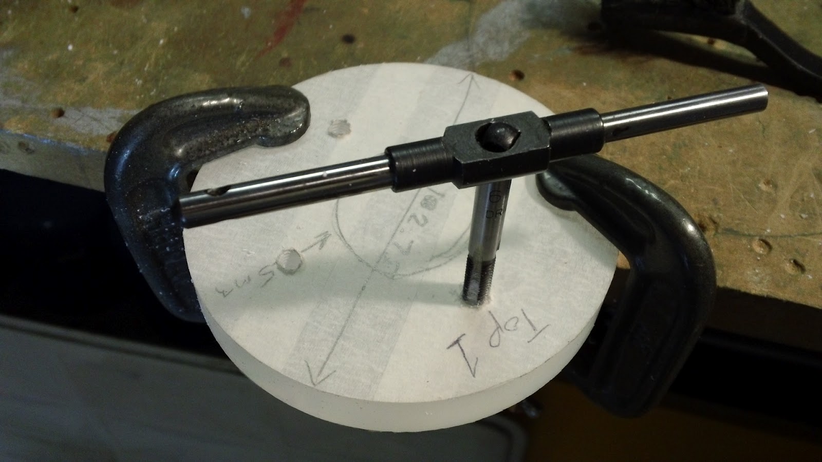
Here I am taping the four 5mm holes in the bottom acrylic disc to accept the M6 nylon bolts. Remember, this is the disc that will be bonded to the top cap of the secondary.
After removing all the protective masking tape I did a quick trial assembly just to make sure everything lined up OK.
And here's the mount in situ, not bonded yet, that will have to wait till the secondary is wound. That's the next job.

If you like this blog you can show your support by one or all of these. 1. +1 my blog and email it to a friend. 2. Follow me.... It's good to know someones interested. 3. Leave a comment.... All are appreciated.

Tuesday, 5 June 2012

Secondary Coil (Take 2)


A couple of weeks back I spent a few of hours playing with my oscilloscope. I had seen a few articles on the web showing how to measure the resonant frequency of the primary and secondary coils with an oscilloscope so I thought I would give it a try. The easiest one to measure is the secondary coil, to do it accurately you need to remove the primary coil and simulate streamers from the toroid as these change the resonant frequency. I was not looking for this degree of accuracy at this stage, really just having a go to get a rough idea.
I disconnected the earth lead from the bottom of the secondary coil and connected the coil to the signal generator built in to my oscilloscope.
I plugged a probe into channel one and Damien held the it approximately 3 feet away from the secondary coil.
I set the signal generator to a sine wave of 5v amplitude and starting at 100kHz as I guessed resonance should be between in the range 100kHz to 200 kHz.
The volts per division on channel 1 was set to 10mv and time/div set to 1us. I began to slowly increase the frequency of the signal being supplied to the secondary coil. You can see from the pic above that the trace was flat as 128kHz was passed. This remained the case most of the time as the frequency was increased, there were some signals picked up, presumably harmonics of the true resonance. To my amazement at 175.4kHz the flat trace suddenly transformed into a perfect sine wave, signifying we had hit the resonant frequency of the secondary coil.
As I said this was only done for experimental reasons and in no way to get an accurate resonant frequency, but it did get me thinking more about the relationship between the secondary and primary coils. I had read a lot of references to JAVATC while looking for information about Tesla coil tuning. It's a website based program used to help in the design of Tesla coils. It works by entering lots of component specs and various physical dimensions of the Tesla coil you have built or plan to build. When the program is run it calculates the resonant frequencies of the primary and secondary coil and displays the %tune between them. It can also be used to automatically tune the primary coil to the secondary, in this mode the program will output the correct tap point on the primary (in number of turns) to get resonance with the secondary. It took me a while to work out and gather all the different data required to test my own Tesla coil build but after a lot of measuring I entered the data into JAVATC.

CRAP!!!
According to the software I needed to tap my primary coil at turn 16 to get resonance with the secondary coil. That would be a slight problem. I only have 12.5 turns on my primary!!! The reason for this was a lack of understanding when turning my secondary coil. I had opted for a larger secondary coil during the build after choosing a few other upgrades. I had failed to upgrade the magnet wire gauge used to form the windings. The 0.4mm diameter wire I used on the larger secondary had resulted in far more turns than required. There is only one thing for it, build another secondary with less turns.

If you like this blog you can show your support by one or all of these. 1. +1 my blog and email it to a friend. 2. Follow me.... It's good to know someones interested. 3. Leave a comment.... All are appreciated.

Sunday, 30 October 2011

Still finishing the Secondary

Managed to get the holes drilled to mount the secondary coil to its base. I had to drill them free hand as the base is too large to fit under my milling machine. There are eight 8mm holes.
Here you can see the secondary coil mounted on the base. The copper lug on the right is attached underneath the head of a steel bolt and this will make the secondary coil electrical connection to ground.
The end of the secondary is soldered into a small piece of 1/8" copper piping which provides a better material for the copper lug to clamp onto.
The eight bolts pass through the base and are secured with matching nuts on the underside. Another copper lug will be placed on the steel bolt to allow connection to ground.
Coco was not at all interested in the secondary coil base.
I think I will run the ground connection from a copper lug on the steel bolt out to one of the pairs of supporting perspex columns and down into the base.


If you like this blog you can show your support by one or all of these.


1. +1 my blog and email it to a friend.
2. Follow me.... It's good to know someones interested.
3. Leave a comment.... All are appreciated.

Saturday, 29 October 2011

Finishing the Secondary Coil

Just finished coat of varnish number six. That's it, feels pretty smooth now so I am going to say it's done. After allowing to dry properly (about an hour) I removed the coil from the winding jig.
I removed the bottom end plate from the secondary coil which allowed me to mark up the perspex disc which would support both the secondary and primary coil. This was easily achieved by simply using the end plate as a stencil.
The above pic shows the hole positions marked, behind is the secondary coil base plate with the mounting bolts in place.
The mounting bolts are 7 X 6mm nylon and one steel 6mm bolt. The steel bolt has a copper lug fitted under the head. This steel bolt will be connected to the bottom winding of the secondary coil and will complete the connection to ground through the perspex mounting disc. I think this is a really neat idea and will mean the secondary coil can be easily removed.
Will drill the holes in the mounting disc tomorrow and post a few pics of the secondary coil in situ.