I was hoping to finish off the top and bottom coil end caps today but this didn't work out. I needed to bond an acrylic plug into the central hole in the bottom cap. This is to close up the hole needed to mount the coil in the winding jig.
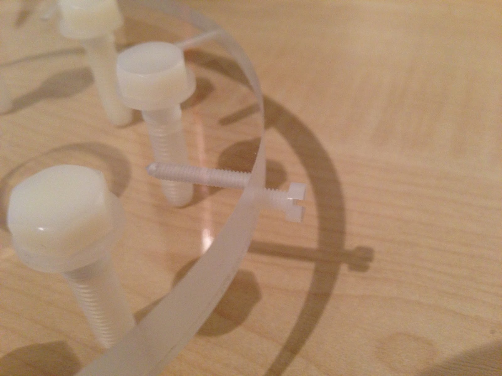
I also trial fitted the eight nylon bolts that will hold the coil down onto the Tesla body.
Here's a close-up of the plug in place. I also planned to bond the toroid mounting assembly to the top cap of the coil. This would, again, close up the hole needed for the winding jig.
Bonding was going to be achieved by using Tensol acrylic cement which a had purchased a while back from Trent Plastics. When I dug out the bottle the liquid was thicker than I had anticipated. From videos I had seen, bonding sheet acrylic was done using a water-like solvent that used capillary action to penetrate between two close fitting acrylic sheets. The liquid I had was like syrup and there was no way this would seep into a fine gap. I assumed all Tensol was the same and you know what they say about assumption. After a bit of investigating I think I have Tensol 12 which can be used for bonding gaps between rougher cut acrylic pieces. Tensol 70 is the version more suited for close fitting sheet acrylic but it was averaging out at £40 and minimum qty 500ml. Too much and too much. More homework was needed.
Here's what I found out. These water-like acrylic cements don't actually "glue" things together. It's more like a weld. The solvent dissolves the surfaces of the two pieces and the molecules merge from either side. The solvent evaporates and the two pieces become one. The solvent in these cements is Methylene Chloride also known as Dichloromethane. It's pretty nasty stuff but apparently it's all you need to bond close fitting acrylic and you can get it from eBay or Amazon. I paid £4.79 for 250ml, delivery was almost £8.00 because of it's hazardous nature. It should turn up tomorrow so will try it and let you know.
Anyway, crack on. I bought some shorter (12mm) cheese head slotted M4 nylon screws to fix the top and bottom caps in place. The 20mm bolts are a bit excessive!
If you like this blog you can show your support by one or all of these.
1. +1 my blog and email it to a friend.
2. Follow me.... It's good to know someones interested.
3. Leave a comment.... All are appreciated.
This is my blog of current hobbies, at the moment that happens to be all things Tesla so I have decided to build a Tesla coil and, as usual, I will go completely over the top with it.
Showing posts with label tesla secondary coil. Show all posts
Wednesday, 29 May 2013
Monday, 27 May 2013
Secondary Coil Ground Terminal
I have just finished the lower electric connection to the secondary coil. As explained in previous posts this connection is made up of a 70mm x 23mm copper plate on the side of the secondary coil. The plate will be glued in place using 2 part epoxy. After deciding the final position of the copper plate I surrounded the area with masking tape, not really to offer any protection to the surrounding area, just as a guide. The inside of the area was deeply scored with sharp craft knife to produce a good key for the epoxy.
The copper plate was tinned (to aid soldering) and then the lower lose tail of the windings stripped of varnish and soldered to the copper plate. I used my new Dremel VersaTip to do the tinning and soldering. I bought it really to use as a small blow torch for tinning and delicate metal work, however I was very impressed with its soldering capabilities.
Here's a shot of the tail end of the windings attached to the copper terminal. The back of the plate was cleaned up with a brass wire wheel on the Dremel 8200 then cleaned with meths to remove all soldering residues. I removed the masking tape from around the scored hatchings on the coil, this would allow me to position the plate better by eye.
I mixed up a blob of 2 part 5 minute epoxy glue and applied it to the back of the copper terninal plate. Forgot to mention I had cross-hatched the back of the plate to aid bonding.
I positioned the plate onto the coil and lined it up parallel with the windings and made sure the lose tail was positioned nicely around the coil and taught. I held in position for about 5 mins while the epoxy hardened.
The plate got warm as the epoxy went off, so easy to judge when it was safe to release pressure. I neatly positioned the tailing winding wire so it made a nice spiral from the end of the windings to the copper terminal.
Then I used a small brush to cover the tailing wire with insulating varnish which will protect and hold the wire in place on the form. I gave the tail wire 3 coats.
Here's the finished terminal. Think it looks pretty good.
If you like this blog you can show your support by one or all of these. 1. +1 my blog and email it to a friend. 2. Follow me.... It's good to know someones interested. 3. Leave a comment.... All are appreciated.
The copper plate was tinned (to aid soldering) and then the lower lose tail of the windings stripped of varnish and soldered to the copper plate. I used my new Dremel VersaTip to do the tinning and soldering. I bought it really to use as a small blow torch for tinning and delicate metal work, however I was very impressed with its soldering capabilities.
I mixed up a blob of 2 part 5 minute epoxy glue and applied it to the back of the copper terninal plate. Forgot to mention I had cross-hatched the back of the plate to aid bonding.
I positioned the plate onto the coil and lined it up parallel with the windings and made sure the lose tail was positioned nicely around the coil and taught. I held in position for about 5 mins while the epoxy hardened.
The plate got warm as the epoxy went off, so easy to judge when it was safe to release pressure. I neatly positioned the tailing winding wire so it made a nice spiral from the end of the windings to the copper terminal.
Then I used a small brush to cover the tailing wire with insulating varnish which will protect and hold the wire in place on the form. I gave the tail wire 3 coats.
Here's the finished terminal. Think it looks pretty good.
If you like this blog you can show your support by one or all of these. 1. +1 my blog and email it to a friend. 2. Follow me.... It's good to know someones interested. 3. Leave a comment.... All are appreciated.
Thursday, 23 May 2013
Winding the Secondary Coil for the second time.
The new secondary coil form has been sat in my homemade coil winder for long enough. It's time to start winding.
In my last post I gave the new stats for the replacement coil. The only change I have made is to start the windings 4.5cm from the base of the coil rather than 4.0cm. This change is just to allow a little extra room at the base of the coil to accomodate the copper plate that will act as the lower electrical connection. This will mean with the same number of turns (1050) the windings will finish 0.5cm higher, 8.3cm from the top of the coil.
Before starting the winding I thoroughly cleaned the outside of the coil with meths to remove all traces of grease. I ran a line of masking tape around the coil with the top edge of the tape exactly 4.5cm from the base of the form. This would ensure that the windings would start exactly level with the base of the form. I measured 67.2cm (total height of windings required) from the top edge of the tape and marked this point on the form with a small pen dot. I would coil tightly up to this point then loose coil to the top of the form.
Well almost ready to start. Not quite. This time there's no help available..... and believe me, its better to have an extra pair of hands when winding a coil especially if you are relying on human resources to tension the feed wire and direct the winding wire onto the coil. Manual winding requires both hands, one to feed the wire (left in my case) and the other hand to push the coils together either with a non scratch implement or the back of your finger nail. This means you have no free hands if you need to stop (or start) the winding motor. My winding motor is powered by a variable power supply on the bench the winding jig, not exactly "to hand". I would need some way to switch it on/off remotely.
Bingo. Idea.
I plugged the power supply into one off those remote control mains switches. This one is a cheap as chips version from Maplin similar to the one linked.
Here's the little controller. I can either have it close to hand or even put it on the floor and press the off button with a press of a toe.
The winding wire end was clamped under the head of one of the white plastic bolts that holds the base coil end in place. You need to have a plan in place to clamp the wire end tight when you finish the windings, I decided to clamp it with the same method as the start, using one of the bolts that holds the top coil end in place.
Time to turn.
Well it took about an hour and went pretty well. Stopped just once when I realised I had left the door open. Two kittens and turning a tesla secondary coil are not compatible. Here's a quick vid of the finished coil. I have put on a couple of coats of insulating varnish. Still needs another couple of coats.
I am really happy with the finish. The varnish has a better finish than on my first coil. Next up is a few more coats and then fitting the copper plate electrical connection at the base of the coil.
If you like this blog you can show your support by one or all of these. 1. +1 my blog and email it to a friend. 2. Follow me.... It's good to know someones interested. 3. Leave a comment.... All are appreciated.
In my last post I gave the new stats for the replacement coil. The only change I have made is to start the windings 4.5cm from the base of the coil rather than 4.0cm. This change is just to allow a little extra room at the base of the coil to accomodate the copper plate that will act as the lower electrical connection. This will mean with the same number of turns (1050) the windings will finish 0.5cm higher, 8.3cm from the top of the coil.
Before starting the winding I thoroughly cleaned the outside of the coil with meths to remove all traces of grease. I ran a line of masking tape around the coil with the top edge of the tape exactly 4.5cm from the base of the form. This would ensure that the windings would start exactly level with the base of the form. I measured 67.2cm (total height of windings required) from the top edge of the tape and marked this point on the form with a small pen dot. I would coil tightly up to this point then loose coil to the top of the form.
Well almost ready to start. Not quite. This time there's no help available..... and believe me, its better to have an extra pair of hands when winding a coil especially if you are relying on human resources to tension the feed wire and direct the winding wire onto the coil. Manual winding requires both hands, one to feed the wire (left in my case) and the other hand to push the coils together either with a non scratch implement or the back of your finger nail. This means you have no free hands if you need to stop (or start) the winding motor. My winding motor is powered by a variable power supply on the bench the winding jig, not exactly "to hand". I would need some way to switch it on/off remotely.
Bingo. Idea.
I plugged the power supply into one off those remote control mains switches. This one is a cheap as chips version from Maplin similar to the one linked.
Here's the little controller. I can either have it close to hand or even put it on the floor and press the off button with a press of a toe.
Time to turn.
Well it took about an hour and went pretty well. Stopped just once when I realised I had left the door open. Two kittens and turning a tesla secondary coil are not compatible. Here's a quick vid of the finished coil. I have put on a couple of coats of insulating varnish. Still needs another couple of coats.
I am really happy with the finish. The varnish has a better finish than on my first coil. Next up is a few more coats and then fitting the copper plate electrical connection at the base of the coil.
If you like this blog you can show your support by one or all of these. 1. +1 my blog and email it to a friend. 2. Follow me.... It's good to know someones interested. 3. Leave a comment.... All are appreciated.
Sunday, 16 December 2012
A turn around the secondary coil. Again.
Hi everybody, not done a post for ages. Been busy with a bit of decorating and think I have not been looking forward to re-doing the secondary coil so have kept putting it off. I think it's time to finish the secondary so I can get on with testing and finally fire up this monster. Plus I think I need to move the Tesla to a safer area, at the moment it's in our freshly decorated living room which used to be pretty safe place where it wouldn't get damaged. Not anymore! Sadly we lost our old cat, Coco, a couple of months back but acquired 2 little rescue kittens, Milo and Lulu. They are mad. I haven't yet worked out if Perspex is claw proof and my Tesla looks like the worlds biggest scratching post.
If you want to see Milo and Lulu live take a gander at http://cats.damow.net from 10am till 4pm weekdays or anytime after 11pm any day. Live webcam of our kitchen (cats bedroom).
Anyway on with the Tesla. I have finalised the design for the windings on the secondary coil. The goal was to reduce the number of turns and this was achieved by increasing the diameter of the magnet wire on the secondary and reducing the length of the windings. I used JAVATC to generate the figures I needed.
With 1050 turns on the secondary resonance should be achieved by tapping the primary coil at turn number 11. The predicted resonant frequency is just over 180kHz and can be seen in the data below.
The new secondary coil blank is installed on my trusty winding jig. So glad I decided not to sell the jig on eBay after completing the first doomed secondary.
I made a small change to the winding jig. I replaced the original 148:1 motor/gearbox with a 50:1 unit. This should speed up the winding process, last time it took over 3 hours. The motor/gearbox units are produced by MFA and can be obtained from Maplin in a variety of ratios.
I have already purchased a few bottles of varnish to coat the coil after the windings are done. I am using the same as last time, it's made by a company called AEV (Advanced Electrical Varnishes) and is known as Ultimeg 2000/372 a high build Alkyd air drying anti-tracking varnish. The easiest place to get it is from Brocott on eBay but it's expensive in small amounts (£4.50 for 100ml plus p+p). You can also buy it from Hi-Wire Ltd for about £28 plus p+p but the smallest qty is 5 litres.
If you like this blog you can show your support by one or all of these. 1. +1 my blog and email it to a friend. 2. Follow me.... It's good to know someones interested. 3. Leave a comment.... All are appreciated.
If you want to see Milo and Lulu live take a gander at http://cats.damow.net from 10am till 4pm weekdays or anytime after 11pm any day. Live webcam of our kitchen (cats bedroom).
Anyway on with the Tesla. I have finalised the design for the windings on the secondary coil. The goal was to reduce the number of turns and this was achieved by increasing the diameter of the magnet wire on the secondary and reducing the length of the windings. I used JAVATC to generate the figures I needed.
With 1050 turns on the secondary resonance should be achieved by tapping the primary coil at turn number 11. The predicted resonant frequency is just over 180kHz and can be seen in the data below.
The new secondary coil blank is installed on my trusty winding jig. So glad I decided not to sell the jig on eBay after completing the first doomed secondary.
I made a small change to the winding jig. I replaced the original 148:1 motor/gearbox with a 50:1 unit. This should speed up the winding process, last time it took over 3 hours. The motor/gearbox units are produced by MFA and can be obtained from Maplin in a variety of ratios.
I have already purchased a few bottles of varnish to coat the coil after the windings are done. I am using the same as last time, it's made by a company called AEV (Advanced Electrical Varnishes) and is known as Ultimeg 2000/372 a high build Alkyd air drying anti-tracking varnish. The easiest place to get it is from Brocott on eBay but it's expensive in small amounts (£4.50 for 100ml plus p+p). You can also buy it from Hi-Wire Ltd for about £28 plus p+p but the smallest qty is 5 litres.
If you like this blog you can show your support by one or all of these. 1. +1 my blog and email it to a friend. 2. Follow me.... It's good to know someones interested. 3. Leave a comment.... All are appreciated.
Saturday, 29 October 2011
Finishing the Secondary Coil
Just finished coat of varnish number six. That's it, feels pretty smooth now so I am going to say it's done. After allowing to dry properly (about an hour) I removed the coil from the winding jig.
I removed the bottom end plate from the secondary coil which allowed me to mark up the perspex disc which would support both the secondary and primary coil. This was easily achieved by simply using the end plate as a stencil.
The above pic shows the hole positions marked, behind is the secondary coil base plate with the mounting bolts in place.
The mounting bolts are 7 X 6mm nylon and one steel 6mm bolt. The steel bolt has a copper lug fitted under the head. This steel bolt will be connected to the bottom winding of the secondary coil and will complete the connection to ground through the perspex mounting disc. I think this is a really neat idea and will mean the secondary coil can be easily removed.
Will drill the holes in the mounting disc tomorrow and post a few pics of the secondary coil in situ.
I removed the bottom end plate from the secondary coil which allowed me to mark up the perspex disc which would support both the secondary and primary coil. This was easily achieved by simply using the end plate as a stencil.
The above pic shows the hole positions marked, behind is the secondary coil base plate with the mounting bolts in place.
The mounting bolts are 7 X 6mm nylon and one steel 6mm bolt. The steel bolt has a copper lug fitted under the head. This steel bolt will be connected to the bottom winding of the secondary coil and will complete the connection to ground through the perspex mounting disc. I think this is a really neat idea and will mean the secondary coil can be easily removed.
Will drill the holes in the mounting disc tomorrow and post a few pics of the secondary coil in situ.
Friday, 30 September 2011
Secondary base finished
Just got in from the garage. Spent a couple of hours drilling and tapping the holes in the secondary coil and the bottom disc.
The eight holes around the perimeter are tapped to accept 20mm M4 bolts which will pass through corresponding 4mm holes in the secondary coil. The other eight holes started as 7mm plain holes and were then tapped to M8. They will be used to bolt the secondary coil down to the base.
The holes were drilled with the disc in situ inside the secondary coil. The drill size required is 3.3mm. After drilling the components were separated and the disc tapped to M4. The 3.3mm holes in the secondary were opened up to 4mm.
Here you can see the base disc bolted inside the secondary coil. Think it looks great and, as usual, completely over engineered.
I have used nylon bolts, not sure if it would be OK to use metal so opted for nylon.
The eight holes around the perimeter are tapped to accept 20mm M4 bolts which will pass through corresponding 4mm holes in the secondary coil. The other eight holes started as 7mm plain holes and were then tapped to M8. They will be used to bolt the secondary coil down to the base.
The holes were drilled with the disc in situ inside the secondary coil. The drill size required is 3.3mm. After drilling the components were separated and the disc tapped to M4. The 3.3mm holes in the secondary were opened up to 4mm.
Here you can see the base disc bolted inside the secondary coil. Think it looks great and, as usual, completely over engineered.
I have used nylon bolts, not sure if it would be OK to use metal so opted for nylon.
Labels:
drilling acrylic,
drilling perspex,
how to build a tesla coil,
joining perspex,
secondary coil,
Secondary coil end cap,
tapping perspex,
tesla coil toroid,
tesla secondary coil,
trent plastics,
winding a scondary coil,
winding secondary coil,
Тесла катушки
Monday, 12 September 2011
Secondary Coil Winding Jig
After reading lots of tesla build diaries and after visiting many HV websites I have realised the only way to create a nice secondary coil is by winding it on some kind of jig. One of the favourite ways is to use a lathe and if the lathe is not long enough to create an "extended" tailstock. Unfortunately my lathe is nowhere near big enough as the chuck is only around 80cm and there's just not enough clearance to spin a length of 110mm (4") pipe. So I have decided to build a jig, but to keep it simple, it will be human powered (son Damien to be exact) and will be big enough to wind up to 6" diameter coils, just in case I want to upgrade from 4" in the future.
One visit to B+Q later. I have
Pack of 2 lengths of 1800mm by 144mm by 20.5mm planed pine.
1 metre length of 10mm threaded bar.
1 metre length of 12mm OD 10mm ID steel tube.
Small bag of 40mm wood screws.
4 10mm plain nuts.
Wood glue.
While at B+Q I got the wood cut to the lengths needed for construction. The cutting service was free and meant all cuts where perfectly square.
The above pic shows the finished article. The base and the backboard are both 900mm long and are glued and screwed along the adjoining edge. The end plates are made by gluing and screwing 2 pieces of 144mm by 144mm by 20.5mm together. The end plates can then be stacked together and drilled at the same time. The hole needs to be 12mm. I then cut 2 40mm lengths of 12mm tube and hammered one into each hole in the end plates. This creates a neat metal bush in each of the wooden end plates. The two end plates were then screwed to the back and base board. I didn't glue them so they can be repositioned if needed.
Here's a closer view of one of the end plates. Doubling up and using 2 pieces of wood provides a bigger bearing for the shaft and also adds extra strength. The 12mm holes are offset to front and top of the end plates. This provides clearance from the base and back board to accomodate a 6" diameter pipe.
Not easy to see, but there is a neat little bush in there which should stop the threads chomping away at the hole.
One visit to B+Q later. I have
Pack of 2 lengths of 1800mm by 144mm by 20.5mm planed pine.
1 metre length of 10mm threaded bar.
1 metre length of 12mm OD 10mm ID steel tube.
Small bag of 40mm wood screws.
4 10mm plain nuts.
Wood glue.
While at B+Q I got the wood cut to the lengths needed for construction. The cutting service was free and meant all cuts where perfectly square.
The above pic shows the finished article. The base and the backboard are both 900mm long and are glued and screwed along the adjoining edge. The end plates are made by gluing and screwing 2 pieces of 144mm by 144mm by 20.5mm together. The end plates can then be stacked together and drilled at the same time. The hole needs to be 12mm. I then cut 2 40mm lengths of 12mm tube and hammered one into each hole in the end plates. This creates a neat metal bush in each of the wooden end plates. The two end plates were then screwed to the back and base board. I didn't glue them so they can be repositioned if needed.
Here's a closer view of one of the end plates. Doubling up and using 2 pieces of wood provides a bigger bearing for the shaft and also adds extra strength. The 12mm holes are offset to front and top of the end plates. This provides clearance from the base and back board to accomodate a 6" diameter pipe.
Not easy to see, but there is a neat little bush in there which should stop the threads chomping away at the hole.
Subscribe to:
Posts (Atom)


