Sunday, 30 October 2011

Still finishing the Secondary

Managed to get the holes drilled to mount the secondary coil to its base. I had to drill them free hand as the base is too large to fit under my milling machine. There are eight 8mm holes.
Here you can see the secondary coil mounted on the base. The copper lug on the right is attached underneath the head of a steel bolt and this will make the secondary coil electrical connection to ground.
The end of the secondary is soldered into a small piece of 1/8" copper piping which provides a better material for the copper lug to clamp onto.
The eight bolts pass through the base and are secured with matching nuts on the underside. Another copper lug will be placed on the steel bolt to allow connection to ground.
Coco was not at all interested in the secondary coil base.
I think I will run the ground connection from a copper lug on the steel bolt out to one of the pairs of supporting perspex columns and down into the base.


If you like this blog you can show your support by one or all of these.


1. +1 my blog and email it to a friend.
2. Follow me.... It's good to know someones interested.
3. Leave a comment.... All are appreciated.

Saturday, 29 October 2011

Finishing the Secondary Coil

Just finished coat of varnish number six. That's it, feels pretty smooth now so I am going to say it's done. After allowing to dry properly (about an hour) I removed the coil from the winding jig.
I removed the bottom end plate from the secondary coil which allowed me to mark up the perspex disc which would support both the secondary and primary coil. This was easily achieved by simply using the end plate as a stencil.
The above pic shows the hole positions marked, behind is the secondary coil base plate with the mounting bolts in place.
The mounting bolts are 7 X 6mm nylon and one steel 6mm bolt. The steel bolt has a copper lug fitted under the head. This steel bolt will be connected to the bottom winding of the secondary coil and will complete the connection to ground through the perspex mounting disc. I think this is a really neat idea and will mean the secondary coil can be easily removed.
Will drill the holes in the mounting disc tomorrow and post a few pics of the secondary coil in situ.

Wednesday, 26 October 2011

Primary thoughts

As the secondary coil is pretty much finished I have already been thinking about construction of the primary coil. Both coils will sit on a perspex 50cm 12mm thick disc which is supported above the second layer of the main module on 8 30mm diameter 20cm long perspex pillars.
The second level contains the MMC module, the spark gap module and a step down transformer module for the spark gap motor. All modules are mounted on ceramic standoffs.
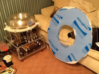
I have yet to finish off wiring and the support disc is not yet fitted. As you can see I have coated it in masking tape ready for marking up the holes for drilling.
The pillars are drilled out to 5mm and then threaded to take M6 bolts. If you want some advice for drilling and tapping perspex takes a look at my Drilling and Tapping Perspex page.
The primary and secondary coil will sit on the top perspex disc (covered in masking tape above). At this point I have decided to upgrade the design from the original plans (yet again). I thought it would be a good idea to mount the primary coil underneath a perspex disc which should help prevent strikes to the primary coil. Also I heard if you do this any strikes that hit the perspex create an interesting effect as they spread out over the perspex. I will install a more traditional strike rail around the edge of this protection disc. The disc diameter was decided at 90cm and it would need a 170mm diameter central cut-out to allow the 150mm diameter secondary coil to pass through.
And here it is. Ordered from Trent Plastics, it turned up at work this morning. Took me about 10 minutes to remove the 3 layers of cardboard packaging.
The thickness is 5mm and I paid extra to have the inside and outside edges polished. It's a big piece of plastic and does flex a little, but there will be 8 radial combs from the centre outwards to support the primary coil and these will add extra stiffness.

Tuesday, 25 October 2011

Varnishing Secondary Coil

Have now had my secondary coil mounted in the winding jig for a couple of weeks. It seems to be taking ages to get the correct amount of anti tracking varnish on the coil. I have just applied the forth coat.
I have applied each coat by brush with the winding jig rotating at about 5rpm. It's a good way of holding the coil while its being varnished plus the rotation helps prevent runs from forming. As you can see after coat number 4 the coil seems to have a gloss finish. However on closer inspection.....
.....you can see there are still areas that have not been been completely covered by varnish. I have ordered another bottle of varnish which should give me another 2 layers which, hopefully, will give the full gloss cover over the whole coil.
I've noticed that you can still feel the individual turns in the areas that are not fully covered so I think I will use the rule that when it feels smooth it's got enough coats.

Sunday, 16 October 2011

Winding the Secondary Coil

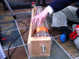
Now that the toroid has finally arrived I am keen to finish off the secondary coil so I can progress on to the primary. The next step is to wind the secondary. The windings will be as per the instructions, 26awg wire which is 0.40mm diameter. When measured with my verniers I get an average of 0.44mm which (I presume) is due to the insulating varnish coating on the wire. The wire will be wound onto my 6" perspex form which measures 810mm. The windings will be 28" high centred on the perspex tube. I will be using my recently upgraded (now motorized) winding jig.
Above you can see the coil former fitted on to the jig. I calculated that there would be just over 1600 turns on the coil each single turn being 471mm (150mm X 3.141) so a total length of 753 metres of wire!
   The winding jig is geared to turn at 15rpm running at a maximum 12 volts so 1600 turns would take 106 minutes minimum.
I started the winding by passing the wire through 3 tiny holes, first in then out then back inside the former, leaving about 6" inside to work with. With the motor running I started to lay down the first few turns. I used my left hand to guide the wire onto the form and a finger nail on my right hand to keep the coils pushed up against each other (if needed). I soon realised that 15rpm was a little fast and backed the bench supply back to 10 volts. Also this is definitely easier as 2 person job. I needed my son (Damien) to help make alterations to rpm, stop and start the jig when the turnings accidently overlap, reposition the feed spool and countless other help during what turned out to be 3 hours of boredom occasionally broken up with moments of intense panic.
The pic above shows the finger nail guide technique which proved to be quite successful. In my left hand you can see a piece of material which I used to create a bit of tension on the wire.
It's best to feed the wire onto the coil slightly behind the present position on the former. This means the last coil on the tube helps guide on the next turn.
Here's a quick video that shows a little of the winding process. Sorry about the annoying noise the winding jig makes. We had to listen to it for 3 hours so think yourself lucky!
We have done a longer video which Damien is going to process and convert into a time lapse. We will post it to youtube and stick a link in here when it's done.


Three hours later and the coil was finished. Could help sticking it in place with the toroid just to get an idea of the finished TC.
Damien's arty shot. We are about to decorate so no comments on the pink flowery wall paper please.

If you like this blog you can show your support by one or all of these.

1. Click on some ads shown on this blog.... I get paid for that.
2. Follow me.... It's good to know someones interested.
3. Leave a comment.... All are appreciated.

Spun Aluminium Toroid

Saturday morning brought a knock at the door. It was the Parcel Force guy with a large box all the way from Backus, Minnesota in the US.
 I knew it must be my upgraded Toroid sourced for me by Alan from Teslastuff. Instead of the original 12" toroid I had decided to go for an 18" by 4.5" to make full use of the other upgrades I had done. I had approached a couple of metal spinning companies in the UK to see if I could get an 18" toroid made, making it would be easy but I would also have to pay for the tooling to be made and this would be a fortune. Alan from Teslastuff came to the rescue and managed to get me a O.W. Landergren spun aluminium seamless 18" toroid. It wasn't cheap and I was about to find out if it was worth it.
I carefully opened the top edge and removed a thick piece of cardboard and then some paper packaging. I got my first glimpse of the toroid in a protective plastic bag. It was big.
Carefully pulled it out and lay it flat on top of the box. It was heavier than I thought. I removed it from the bag and had a close look.
I was very impressed. There is no sign of the welded seam, it is finished off beautifully, a substantial piece of aluminium. I measured the thickness of the aluminium through the central hole, approx 7mm. This thickness is the 2 pieces aluminium that make up the completed toroid, so I presume each side of the toroid starts off life as a 1/8" thick aluminium disc prior to spinning and welding.
The toroid is the most obvious part of a Tesla coil and I thought it important to make it match or exceed the high aesthetic value I have been trying to work to. I know this one does.

Sunday, 9 October 2011

Winding Jig Upgrades

I finished the secondary coil winding jig a few weeks back and was planning to wind the coil by spinning the perspex tube by hand. After deciding to upgrade to a 6" coil and reading lots more winding stories on the web I have decided to upgrade my jig by adding a motor.
The picture above shows the finished winding jig in its manual mode to speak. The easiest way to rotate the secondary coil would be to drive it directly with a rubber drive belt otherwise I would have to drive the central shaft and fix the perspex former to it. Direct drive to the coil tube via rubber belt was chosen and the parts quest was on.
    I would need a motor with a suitable gearbox, a pulley to fit the output shaft and a rubber drive belt. First place I tried was Maplin, I had bought a similar motor from there in the passed to power the belt on a Van der Graaf generator I made. They had the motor I needed but not the belt or a suitable pulley so I carried on looking. I found everything I needed at Technobots they had an excellent choice of motors, pulleys and drive belts, they took Paypal and delivered the stuff within a few days. I was aiming for  a coil rotational speed of around 15rpm so a bit of maths was needed to work out gearbox ratio, pulley size and drive belt diameter. Final positioning of the motor on the jig is really by trial and error, you just need to get the right tension on the drive belt so it doesn't slip as you are winding. I had to mount the motor on a small piece of wood to get the correct spacing.
The motor I used was a 540 size motor that came with a 148:1 reduction gearbox. The mounting plate comes with it, the output shaft is 6mm and it can be run on 4.5v to 15v.
I needed to make a small cut out on the back panel of the jig to allow clearance for the drive belt. The upgrade was finished and it went quite well to say that I hadn't designed the jig to take a motor to start with.
I also knocked together a spool support for the 26awg wire. This would need to allow the feed spool to rotate freely so I did my typical over engineering on it. Starting with an old piece of wood and a length of 10mm aluminium rod.
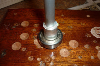
I had a sealed bearing with a 10mm ID to hand so I turned a 10mm ID X 16mm OD 3mm spacer which went onto the 10mm vertical aluminium shaft followed by the bearing.
Then another 10mm ID X 16mm OD spacer, this time 15mm deep.
Then the spool itself then another spacer/bush to keep the top of the spool centred. Doesn't look pretty but works very nicely.

Saturday, 1 October 2011

Secondary top finished

Have just completed the top end disc for the secondary coil. It's pretty much a carbon copy of the base disc but obviously doesn't require the extra holes for mounting to the base.
As well as the 8 4mm holes around the circumference there is also a central 10mm diameter hole which serves two purposes. Firstly, it allows the top-load to be electrically connected to the coil on the secondary. Secondly, in conjunction with the same hole in the base disc, it allows the whole secondary coil assembly to be mounted on the 10mm shaft of my coil winding jig.
The next job is to wind the coil. This will be the first time winding such a large coil but hopefully should go OK.