I finished the secondary coil winding jig a few weeks back and was planning to wind the coil by spinning the perspex tube by hand. After deciding to upgrade to a 6" coil and reading lots more winding stories on the web I have decided to upgrade my jig by adding a motor.
The picture above shows the finished winding jig in its manual mode to speak. The easiest way to rotate the secondary coil would be to drive it directly with a rubber drive belt otherwise I would have to drive the central shaft and fix the perspex former to it. Direct drive to the coil tube via rubber belt was chosen and the parts quest was on.
I would need a motor with a suitable gearbox, a pulley to fit the output shaft and a rubber drive belt. First place I tried was Maplin, I had bought a similar motor from there in the passed to power the belt on a Van der Graaf generator I made. They had the motor I needed but not the belt or a suitable pulley so I carried on looking. I found everything I needed at Technobots they had an excellent choice of motors, pulleys and drive belts, they took Paypal and delivered the stuff within a few days. I was aiming for a coil rotational speed of around 15rpm so a bit of maths was needed to work out gearbox ratio, pulley size and drive belt diameter. Final positioning of the motor on the jig is really by trial and error, you just need to get the right tension on the drive belt so it doesn't slip as you are winding. I had to mount the motor on a small piece of wood to get the correct spacing.
The motor I used was a 540 size motor that came with a 148:1 reduction gearbox. The mounting plate comes with it, the output shaft is 6mm and it can be run on 4.5v to 15v.
I needed to make a small cut out on the back panel of the jig to allow clearance for the drive belt. The upgrade was finished and it went quite well to say that I hadn't designed the jig to take a motor to start with.
I also knocked together a spool support for the 26awg wire. This would need to allow the feed spool to rotate freely so I did my typical over engineering on it. Starting with an old piece of wood and a length of 10mm aluminium rod.
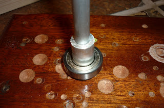
I had a sealed bearing with a 10mm ID to hand so I turned a 10mm ID X 16mm OD 3mm spacer which went onto the 10mm vertical aluminium shaft followed by the bearing.
Then another 10mm ID X 16mm OD spacer, this time 15mm deep.
Then the spool itself then another spacer/bush to keep the top of the spool centred. Doesn't look pretty but works very nicely.


No comments:
Post a Comment