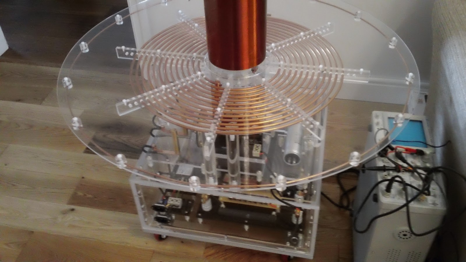
Todays horrible weather gave me a good excuse to do some more work on the Tesla. My next task is to make some kind of easily moveable clamp for the outer connection to the primary coil. It needs to be easily moveable so you can adjust its position (tap point) on the primary coil. The position of the clamp on the primary coil determines the energised length of the primary coil and hence its resonance. The tap point is moved so you can adjust the resonance of the primary to match that of the secondary coil. Well there's the basic tech stuff, here's how I made the clamp.
I started off with a chunk of copper that I picked up off ebay for about £8. It was about 3" long, 1" wide and 3/8" thick. The clamp would have to be of an unusual design because of the perspex disc that covers the whole of the primary coil. I will have to clamp onto the primary coil from below and, depending on the eventual tap point, may have restricted access due to the perspex disc underneath the primary.
After taking a few measurements I made a quick drawing using iDraw on my MacBook just to work out if this design was feasible. I decided this design should work even if the tap point is in the more inaccessible places on the primary coil. The length and shape of the righthand end of clamp may change as the design develops.
The copper block was marked up and sawn into the rough shapes required. The parts were cut slightly larger than required as they would be milled down to the required dimensions.
The off-cut removed was marked up to form the second part and roughly sawn out again oversize to allow for milling.
I fitted a 10mm milling bit and did the first lengthways run to produce the correct thickness required (6mm).
Here's a vid of a bit of the milling process. Milling copper is pretty easy as it's quite soft, I had to use the milling vice because the small height of the pieces I was working on. It's good practice to clamp work as close to the milling bed as possible so any slop in the bed is reduced to a minium. I couldn't do this with these pieces so I kept cut depths small.
After milling the two pieces were clamped together and drilled at the intersect to form the clamp jaws. The primary coil is 1/4" tubing so I used a 1/4" drill bit to form the jaws. To get the jaws to clamp tight on the tube I will remove some of the material at the vertical intersect just below the drilled hole.
A test fit of the piece works fine. It's a tight fit between the coil and the perspex disc underneath so I will mill another 0.5mm off the bottom of the lower assembly.
This picture really shows the need for this particular design of clamp especially if the tap point lies inside the external diameter of the primary coils support disc. Next session I will reduce the clamp thickness, join the two pieces together with some kind of slide mechanism and add the electrical connection.
If you like this blog you can show your support by one or all of these.
1. +1 my blog and email it to a friend.
2. Follow me.... It's good to know someones interested.
3. Leave a comment.... All are appreciated.