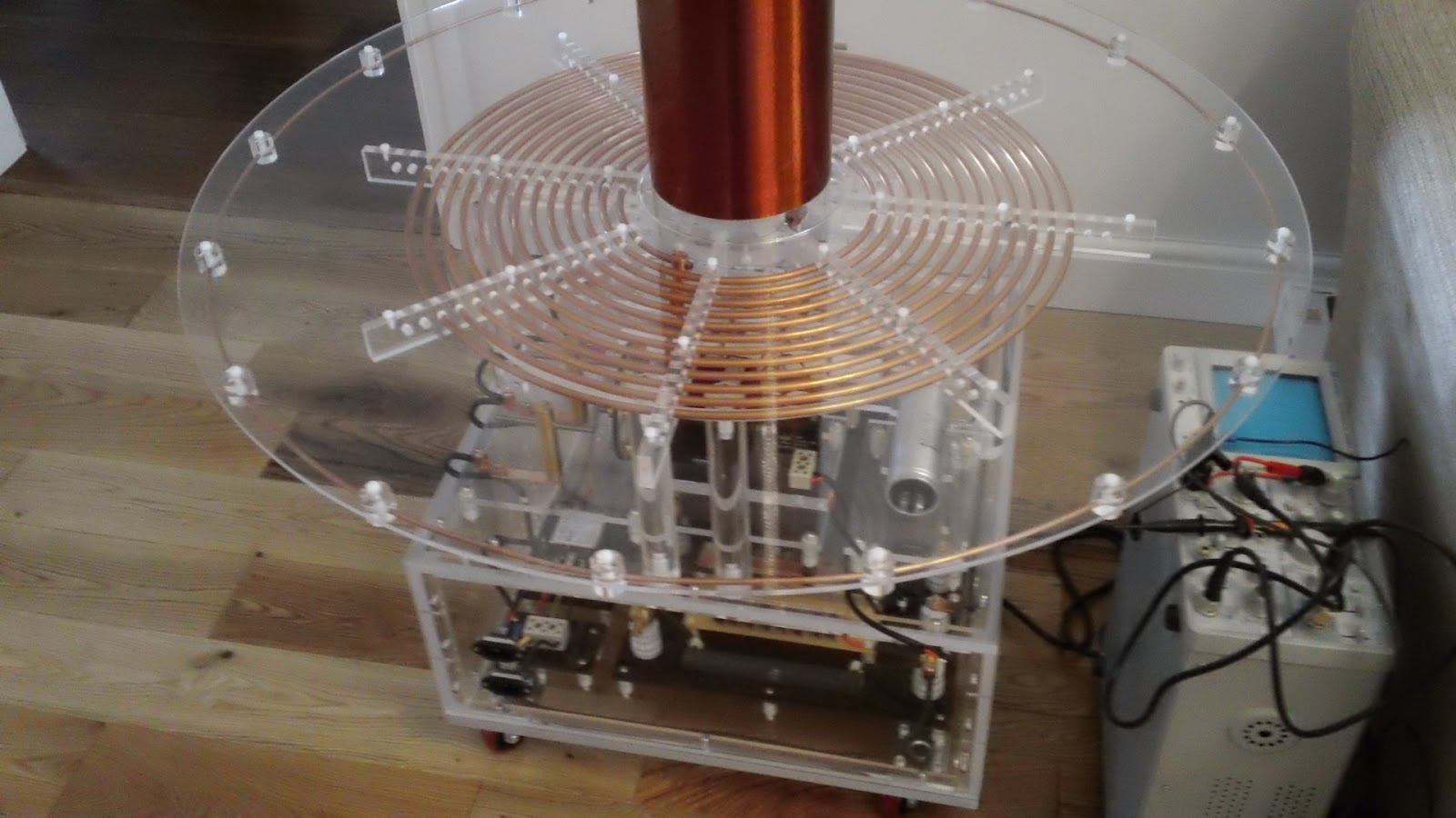
Hi. This must be the last job on my Tesla Coil build. I need to make an earthing point on the main Tesla coil body. Most of the earth leads in my Tesla are connected to the earthing point on the neon transformer. These are
1. Connection to the strike rail underneath the primary coil perspex covering disc.
2. Connection to the lower terminal on the secondary coil.
3. Connection to the central rail on the Terry filter.
So I need to connect this point to my earthing plate on the conservatory wall. I could just run a wire from the earth plate through one of the vent holes in the Tesla base to the earth terminal on the neon transformer. The problem with this solution is that it would be impossible to remove this lead as the ring terminal needed on the end of the wire will not pass through the vent hole. Even if I enlarge the vent hole it would still involve removing one of the perspex walls of the base unit to attach/detach this wire.
After some thought I decided to fit an earthing point on the outside of the back perspex wall of the main Tesla unit. This would consist of 2 copper terminal lugs, one mounted inside, one mounted outside, connected through the perspex by a M6 bolt.
Above is the hardware for the terminal, I will probably replace the stainless M6 bolt with a homemade copper stud but will need to procure an M6 die first.
I made a small lead that finishes in a ring terminal to connect to the new earth point. I fitted the lead to give me a better idea where to site the hole for the terminal.
Marked up the point to drill the 6mm hole. I drilled the hole freehand, there were no obstructions and it was pretty easy to keep the drill at right angles to the perspex.
Result was a nice neat 6mm hole. My OCD placed it on the centre with the vent holes and level with the end of the neon transformer.
Here's the hardware fitted. I used 2 of the copper lugs from Alan at teslastuff.com. These are the best quality electrical lugs I have seen.
The terminal was connected to the short lead from the neon transformer earth point and the perspex sidewall replaced. Job done.
If you like this blog you can show your support by one or all of these.
1. +1 my blog and email it to a friend.
2. Follow me.... It's good to know someones interested.
3. Leave a comment.... All are appreciated.
This is my blog of current hobbies, at the moment that happens to be all things Tesla so I have decided to build a Tesla coil and, as usual, I will go completely over the top with it.
Showing posts with label tesla coil strike rail. Show all posts
Monday, 12 August 2013
Tuesday, 24 April 2012
Electrical connection to the Primary Coil
A few weeks back I made a very nice copper clamp pin which would be used to connect the inner end of the primary coil to the HT lead from the synchronous spark gap (SSG).
The hole at the top will accomodate the inner end of the primary coil and the threaded section will pass through a hole in the primary coil support disc and then the electrical lug will accept the HT lead to the SSG.
First job today was to drill the hole for this clamp pin.
The picture above clearly shows the primary coil support disc, it's the white disc sitting under the radial primary combs. It's white as it still has its protective coating and a layer of masking tape. To drill the hole needed I would need to remove this disc so after marking the hole position I started disassembly. I removed the toroid, the secondary coil and the primary coil assembly which only took a few minutes. The primary coil support disc was removed by undoing the 8 allen key bolts (stainless of course) that screw through the disc into the perspex support columns. I drilled the 9mm hole required for the clamp pin and then removed all the protective coating from the primary coil support disc.
The primary support disc was refitted and the clamp pin slipped over the inner end of the primary coil and the grub screws tightened. The primary coil assembly was then lowered down onto the support disc making sure the clamp pin threaded end lined up with the clearance hole. It did!!
Above is a close look at the clamp pin in situ. Very happy with design, it allows an easily removable electrical connection to the primary coil.
A shot from underneath shows the copper lug bolted to the threaded end of the clamp pin.
I've done a few more pics of the assembled tesla base as this is the first time all protective coatings and masking tape have been removed.
And finally a full length shot with the secondary and toroid back in place.
If you like this blog you can show your support by one or all of these. 1. +1 my blog and email it to a friend. 2. Follow me.... It's good to know someones interested. 3. Leave a comment.... All are appreciated.
The hole at the top will accomodate the inner end of the primary coil and the threaded section will pass through a hole in the primary coil support disc and then the electrical lug will accept the HT lead to the SSG.
First job today was to drill the hole for this clamp pin.
The picture above clearly shows the primary coil support disc, it's the white disc sitting under the radial primary combs. It's white as it still has its protective coating and a layer of masking tape. To drill the hole needed I would need to remove this disc so after marking the hole position I started disassembly. I removed the toroid, the secondary coil and the primary coil assembly which only took a few minutes. The primary coil support disc was removed by undoing the 8 allen key bolts (stainless of course) that screw through the disc into the perspex support columns. I drilled the 9mm hole required for the clamp pin and then removed all the protective coating from the primary coil support disc.
The primary support disc was refitted and the clamp pin slipped over the inner end of the primary coil and the grub screws tightened. The primary coil assembly was then lowered down onto the support disc making sure the clamp pin threaded end lined up with the clearance hole. It did!!
Above is a close look at the clamp pin in situ. Very happy with design, it allows an easily removable electrical connection to the primary coil.
A shot from underneath shows the copper lug bolted to the threaded end of the clamp pin.
I've done a few more pics of the assembled tesla base as this is the first time all protective coatings and masking tape have been removed.
And finally a full length shot with the secondary and toroid back in place.
If you like this blog you can show your support by one or all of these. 1. +1 my blog and email it to a friend. 2. Follow me.... It's good to know someones interested. 3. Leave a comment.... All are appreciated.
Sunday, 1 January 2012
Clamp on strike rail earth connector
Today I fabricated a mock up clamp to earth the strike rail. I started with one of the copper electrical lugs that I bought from Teslastuff.com.
You will not find these listed anywhere on the website or on the Teslastuff eBay shop you will have to email the owner Alan and ask for a price. They are far better quality than anything I have found available in the UK. If you know different drop me an email. I used a length of aluminium 1/2" square rod to make the pieces that form the clamp.
These pieces started off as one block which I drilled with a 12mm bit to form the internal curve and a 6mm bit to form the bolt hole. I used a file to produce the curve on the other end. The block was then cut down the middle using a slotting saw on the milling machine. The two pieces were then clamped back together in a vice on the milling machine and then a 4mm hole drilled exactly on the interface of the two pieces. Using a perfectly flat surface and a piece of fine glass paper I worked the adjoining surfaces this makes the 4mm hole slightly smaller so it clamps tight on the 4mm strike rail.
Here are the assembled pieces. Straight away I spotted an improvement that could be made when fabricating the actual unit, if I put threads on the bolt hole on the top aluminium clamp plate I can dispense with the nut and use a shorter bolt. Also the actual unit will have copper clamping plates to reduce resistance (aluminium 2.7, copper 1.7ohm.m).
I will mount the finished clamp the other way up than shown above. There will be no need to move this clamp once it is in position on the strike rail. But, obviously, access to the grub screw will be needed to clamp the grounding wire.
With the improvements mentioned I think this clamp will do very nicely. Off to eBay to get some copper square rod.
You will not find these listed anywhere on the website or on the Teslastuff eBay shop you will have to email the owner Alan and ask for a price. They are far better quality than anything I have found available in the UK. If you know different drop me an email. I used a length of aluminium 1/2" square rod to make the pieces that form the clamp.
These pieces started off as one block which I drilled with a 12mm bit to form the internal curve and a 6mm bit to form the bolt hole. I used a file to produce the curve on the other end. The block was then cut down the middle using a slotting saw on the milling machine. The two pieces were then clamped back together in a vice on the milling machine and then a 4mm hole drilled exactly on the interface of the two pieces. Using a perfectly flat surface and a piece of fine glass paper I worked the adjoining surfaces this makes the 4mm hole slightly smaller so it clamps tight on the 4mm strike rail.
Here are the assembled pieces. Straight away I spotted an improvement that could be made when fabricating the actual unit, if I put threads on the bolt hole on the top aluminium clamp plate I can dispense with the nut and use a shorter bolt. Also the actual unit will have copper clamping plates to reduce resistance (aluminium 2.7, copper 1.7ohm.m).
I will mount the finished clamp the other way up than shown above. There will be no need to move this clamp once it is in position on the strike rail. But, obviously, access to the grub screw will be needed to clamp the grounding wire.
With the improvements mentioned I think this clamp will do very nicely. Off to eBay to get some copper square rod.
Labels:
anti-strike rail,
bobine de Tesla,
copper clamp,
Forming the primary coil,
make tesla coil,
nikola tesla,
paul walsh,
Strike rail,
strike rail for primary,
strike rail or not,
strike rail vs no strike rail,
strike tube,
tesla coil copper,
tesla coil strike rail
Subscribe to:
Posts (Atom)