Showing posts with label tesla power supply. Show all posts

Tuesday, 24 April 2012

Electrical connection to the Primary Coil

A few weeks back I made a very nice copper clamp pin which would be used to connect the inner end of the primary coil to the HT lead from the synchronous spark gap (SSG).
The hole at the top will accomodate the inner end of the primary coil and the threaded section will pass through a hole in the primary coil support disc and then the electrical lug will accept the HT lead to the SSG.
First job today was to drill the hole for this clamp pin.
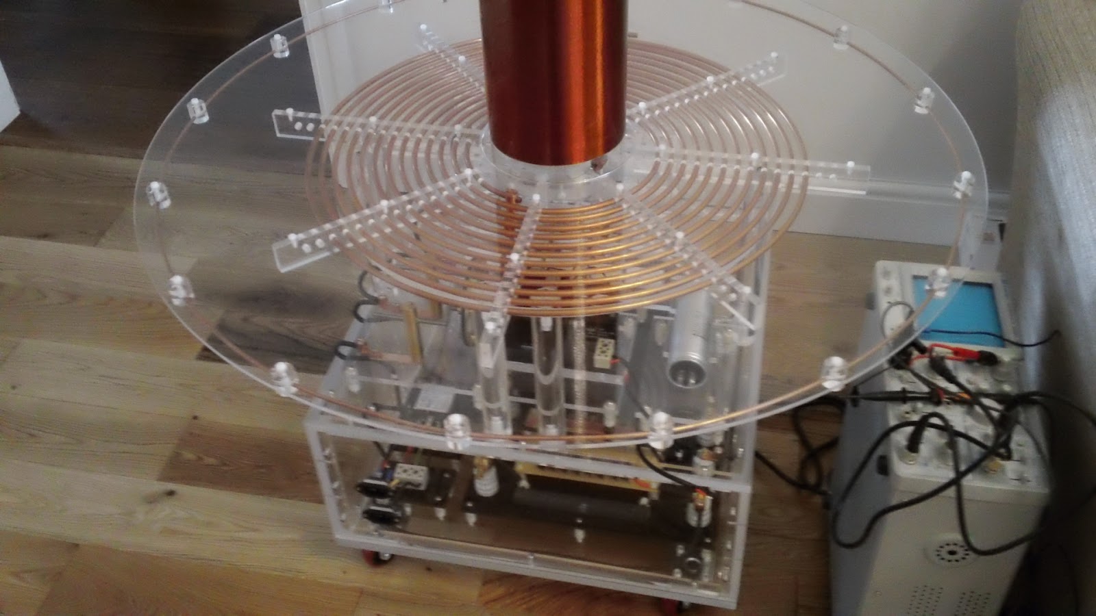
The picture above clearly shows the primary coil support disc, it's the white disc sitting under the radial primary combs. It's white as it still has its protective coating and a layer of masking tape. To drill the hole needed I would need to remove this disc so after marking the hole position I started disassembly. I removed the toroid, the secondary coil and the primary coil assembly which only took a few minutes. The primary coil support disc was removed by undoing the 8 allen key bolts (stainless of course) that screw through the disc into the perspex support columns. I drilled  the 9mm hole required for the clamp pin and then removed all the protective coating from the primary coil support disc.
The primary support disc was refitted and the clamp pin slipped over the inner end of the primary coil and the grub screws tightened. The primary coil assembly was then lowered down onto the support disc making sure the clamp pin threaded end lined up with the clearance hole. It did!!
Above is a close look at the clamp pin in situ. Very happy with design, it allows an easily removable electrical connection to the primary coil.
A shot from underneath shows the copper lug bolted to the threaded end of the clamp pin.
I've done a few more pics of the assembled tesla base as this is the first time all protective coatings and masking tape have been removed.
And finally a full length shot with the secondary and toroid back in place.

If you like this blog you can show your support by one or all of these. 1. +1 my blog and email it to a friend. 2. Follow me.... It's good to know someones interested. 3. Leave a comment.... All are appreciated.

Saturday, 7 January 2012

230V to 110V for Synchronous Motor

Did a little more wiring today. It consisted of connecting one of the female IEC socket in the front panel to the step down transformer on the second level of the tesla coil. I used a length of standard 3A 2 core round black flex. The synchronous motor is rated at 7.5W at 110V so by the equation

                  Power (Watts) = Current (Amps) X Voltage (Volts)

            so   Current (Amps) = Power (Watts)
                                                ------------------
                                                Voltage (Volts)

                                             = 7.5
                                                ----
                                                110

                                             = 0.068 Amps

So, as you can see it draws very little current and even the lightweight 3A cable is a bit of an overkill.
The top IEC socket will supply 240V to the step down transformer which in turn will supply 110V to the synchronous motor. The transformer was sourced from Newlec and came in panel form (uncased) but mounted on a pressed steel bracket. I removed the bracket so I could mount the transformer on a perspex base. This meant that I had to remove the connection strip. This task was undertaken several months back and I thought it would be wise to check that the connections were correct and the transformer is doing what's expected, also a good reason to play with my Xmas present.
The transformer has inputs for 230V and 240V with an output of 110V. I decided to supply a 50Hz AC voltage across the 230V inputs and measure the output of the terminals marked as 110V. I used the function generator built into my oscilloscope to supply this signal to the transformer at a very safe amplitude of about 3 volts. The same signal was feed into channel 2 on the oscilloscope.
The oscilloscope probe was plugged into channel 1 and then connected across the 110V output terminals. With the same volts per division set on both channels and the scope set to dual I could view the input and output waves at the same time. I did take a pic to show you the result but my camera only got an image of a few dots on the oscilloscope screen due to the high speed of the trace. So I took a quick video with my Sony Bloggie.
As you can see, the terminal connection are correct and the transformer is stepping down the voltage by  a factor of about 2 so 230V would be output at about 110V.
I can now finish the wiring to the transformer with confidence. Very pleasing to see actual inputs and outputs on the oscilloscope screen also interesting to see how the 2 signals stay in phase.

Thursday, 22 September 2011

Power Feeds from the Variac

The Tesla coil will need 2 power sources. One variable AC from 0 to 110V for the neon transformer and one fixed 240V AC in to supply the synchronous motor for the spark gap. Both power sources will come from my variac module, obviously the fixed 240V is just taped from the mains feed inside the variac case. The synchronous motor runs at a 110V so the 240V fixed supply runs through a stepdown transformer inside the Tesla coil case. I decided to use 2 IEC female panel connectors to get both power supplies into the Tesla case. They are positioned vertically aligned in one of the perspex sidewalls.
The lower IEC socket connects through a retro looking ceramic terminal block to the EFI/RFI filter and then to the neon transformer.
The hole required for each IEC socket was rectangular with rounded corners and was achieved by drilling four 8mm holes in a rectangle and then using a coping saw to saw from one hole to the next.
Have yet to wire up the top socket which will supply 240V to the stepdown transformer for the synchronous motor.