Showing posts with label tesla coil power supply. Show all posts

Tuesday, 24 April 2012

Electrical connection to the Primary Coil

A few weeks back I made a very nice copper clamp pin which would be used to connect the inner end of the primary coil to the HT lead from the synchronous spark gap (SSG).
The hole at the top will accomodate the inner end of the primary coil and the threaded section will pass through a hole in the primary coil support disc and then the electrical lug will accept the HT lead to the SSG.
First job today was to drill the hole for this clamp pin.
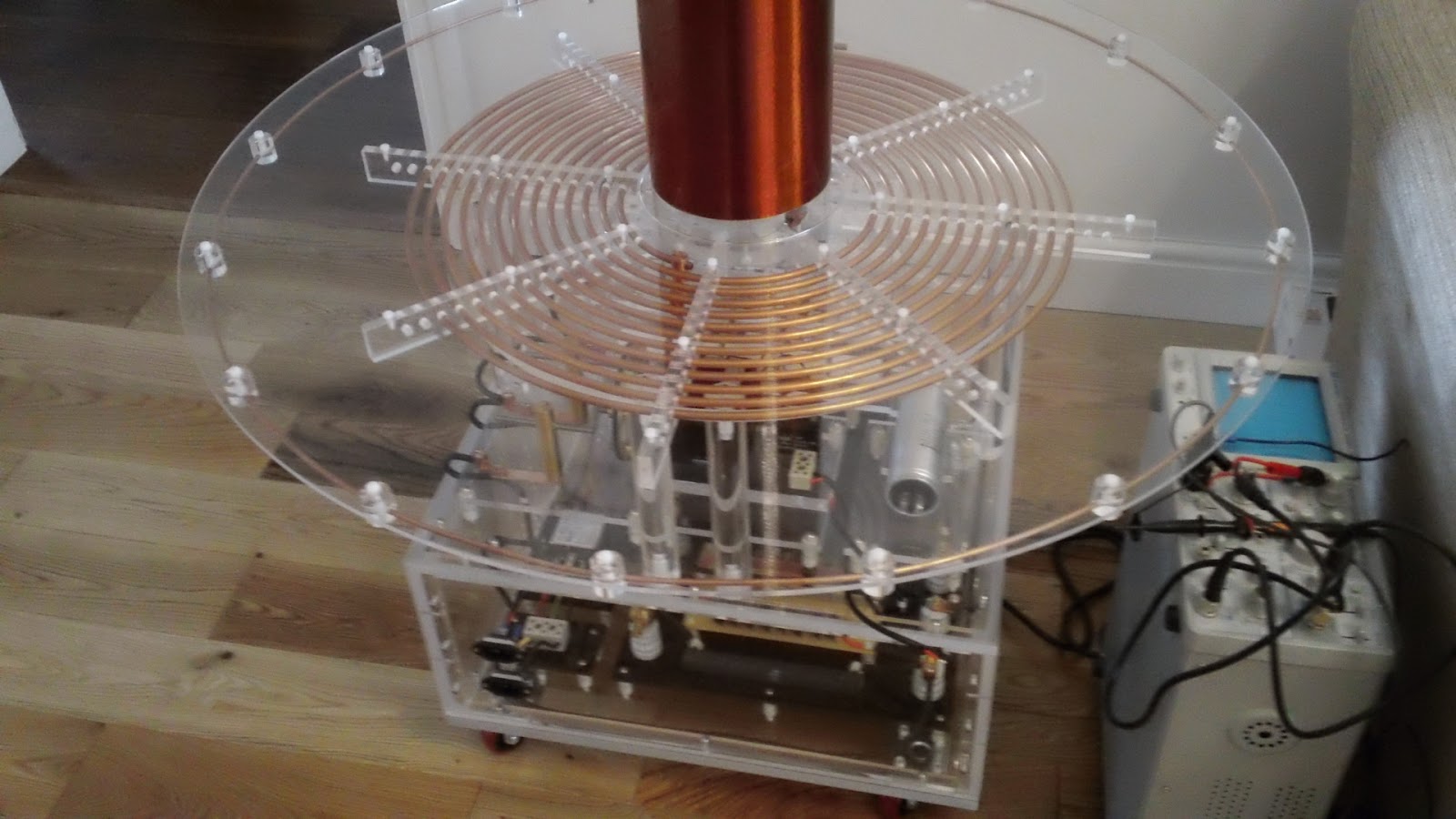
The picture above clearly shows the primary coil support disc, it's the white disc sitting under the radial primary combs. It's white as it still has its protective coating and a layer of masking tape. To drill the hole needed I would need to remove this disc so after marking the hole position I started disassembly. I removed the toroid, the secondary coil and the primary coil assembly which only took a few minutes. The primary coil support disc was removed by undoing the 8 allen key bolts (stainless of course) that screw through the disc into the perspex support columns. I drilled  the 9mm hole required for the clamp pin and then removed all the protective coating from the primary coil support disc.
The primary support disc was refitted and the clamp pin slipped over the inner end of the primary coil and the grub screws tightened. The primary coil assembly was then lowered down onto the support disc making sure the clamp pin threaded end lined up with the clearance hole. It did!!
Above is a close look at the clamp pin in situ. Very happy with design, it allows an easily removable electrical connection to the primary coil.
A shot from underneath shows the copper lug bolted to the threaded end of the clamp pin.
I've done a few more pics of the assembled tesla base as this is the first time all protective coatings and masking tape have been removed.
And finally a full length shot with the secondary and toroid back in place.

If you like this blog you can show your support by one or all of these. 1. +1 my blog and email it to a friend. 2. Follow me.... It's good to know someones interested. 3. Leave a comment.... All are appreciated.

Saturday, 18 June 2011

Worlds nicest Variac

The first bit of the build was to create a case for the variac. I thought it looked really good and it would be a shame to stick it in a metal box. Decided to keep it on display by casing it in perspex. Had lots of small taps and stainless allen key bolts hanging around so decided to bolt it together rather than glue. Trent Plastics was found (eBay again), a supply of many types of plastic sheet and tube. They can supply cut to size so saved me hours of measuring and cutting. The main tube is 250mm diameter 6mm wall, the top holds all the weight so I went for 8mm thick clear perspex. The base is 5mm thick in black cos I thought the base would get scratched pretty quick so clear was probably not a good idea. The next pic shows Variac fitted to top plate and top plate bolted to main tube. Bolts are M3 so not a lot of room for error when drilling holes in the main tube.


After drilling and tapping to fit the base I decided to fabricate some handles which would be fitted to the 4 bolts that mount the Variac to the top plate which meant there would be no stress to the perspex when lifting. Also drilled some vent holes in the base and the top plate, small feet on the base provides clearance for air to enter circulate passed the coils and then out through vent holes in the top plate. Drilled 12mm holes for retro style 20amp switch and 3 10.7mm holes for the glands. The glands have a 12mm 1.5 tpi thread so another ebay purchase was required for the tap and 10.7mm drill bit.


Well happy with the result, handles are solid 16mm aluminium rod, I milled the ends so the M8 x 70 bolts sit nice.


Vent holes are 12mm, you have to go quite slow when drilling otherwise the perspex just melts. Worked well clearing the swarf regularly off the bit. May need more vents, just have to see how it goes.


Switch sits in another 12mm hole. Room for extra vent holes either side of the switch if needed.


Here you can see the 3 glands. One will be 240v mains in, one will be 240v out via switch (may use for quench fan) the other is variable voltage out via the variac. Wiring is the next job.


- Posted using BlogPress from my iPad