Showing posts with label tesla coil design. Show all posts

Monday, 12 August 2013

The final bits.

Hi. This must be the last job on my Tesla Coil build. I need to make an earthing point on the main Tesla coil body. Most of the earth leads in my Tesla are connected to the earthing point on the neon transformer. These are

1. Connection to the strike rail underneath the primary coil perspex covering disc.
2. Connection to the lower terminal on the secondary coil.
3. Connection to the central rail on the Terry filter.

So I need to connect this point to my earthing plate on the conservatory wall. I could just run a wire from the earth plate through one of the vent holes in the Tesla base to the earth terminal on the neon transformer. The problem with this solution is that it would be impossible to remove this lead as the ring terminal needed on the end of the wire will not pass through the vent hole. Even if I enlarge the vent hole it would still involve removing one of the perspex walls of the base unit to attach/detach this wire.

After some thought I decided to fit an earthing point on the outside of the back perspex wall of the main Tesla unit. This would consist of 2 copper terminal lugs, one mounted inside, one mounted outside, connected through the perspex by a M6 bolt.
Above is the hardware for the terminal, I will probably replace the stainless M6 bolt with a homemade copper stud but will need to procure an M6 die first.
I made a small lead that finishes in a ring terminal to connect to the new earth point. I fitted the lead to give me a better idea where to site the hole for the terminal.
Marked up the point to drill the 6mm hole. I drilled the hole freehand, there were no obstructions and it was pretty easy to keep the drill at right angles to the perspex.
Result was a nice neat 6mm hole. My OCD placed it on the centre with the vent holes and level with the end of the neon transformer.
Here's the hardware fitted. I used 2 of the copper lugs from Alan at teslastuff.com. These are the best quality electrical lugs I have seen.
The terminal was connected to the short lead from the neon transformer earth point and the perspex sidewall replaced. Job done.

If you like this blog you can show your support by one or all of these. 1. +1 my blog and email it to a friend. 2. Follow me.... It's good to know someones interested. 3. Leave a comment.... All are appreciated.

Saturday, 3 December 2011

Starting on the Primary Coil

Spent the last few weeks decorating the lounge, those of you who have followed my blog may have spotted the rather flowery decor in some of the pics, for this I apologize but can now confirm that the decor is a little more up to date. Now onto the primary. As per the original plans from Tesslastuff.com I acquired a fifty foot length of 1/4' copper tubing. This can be sourced from many places, I picked a well priced listing on ebay from a seller with a healthy feedback score.
I have spent a long time deciding on the final design of the primary coil, the plans from Tesslastuff.com give you the basic idea and all the correct measurements but, as usual, I wanted to enhance the design with my over engineering. After reading several blogs and coil build diaries there seemed to be two ways to help prevent primary coil strikes (streamers hitting the primary coil- not good). Firstly to fit a ground rail around the primary and secondly to completely cover the primary with a non-conductor. So I decided to do both.
Above is my solution to covering the primary coil. It's a 5mm thick perspex disc with an external diameter of 900mm and an internal diameter of 170mm. The cut-out allows the secondary coil to pass through and as this disc is prominent I want it to be aesthetically pleasing so paid extra for the inside and outside edges to be polished. Here's another pic to give you an idea of the disc size next to the tesla base (room still with old decor).
I would also need some way of supporting the copper tube spiral of the primary. Most people used strips of plastic with evenly spaced cut-outs with accepted the coils of the primary. The coils were secured with glue or by zip ties. I didn't like the idea of glue cos of it's general messiness which doesn't go well when combined with lovely clear perspex. The other option of zip ties just didn't look that good. The best looking install I saw was to use nothing to hold the coils in place. The coil passes through holes drilled in the supports, very neat but a lot harder to achieve. I ordered the material needed for the supports.
These were 8 pieces of 250mm X 30mm X 10mm clear perspex with the top and bottom edges polished.

Sunday, 30 October 2011

Still finishing the Secondary

Managed to get the holes drilled to mount the secondary coil to its base. I had to drill them free hand as the base is too large to fit under my milling machine. There are eight 8mm holes.
Here you can see the secondary coil mounted on the base. The copper lug on the right is attached underneath the head of a steel bolt and this will make the secondary coil electrical connection to ground.
The end of the secondary is soldered into a small piece of 1/8" copper piping which provides a better material for the copper lug to clamp onto.
The eight bolts pass through the base and are secured with matching nuts on the underside. Another copper lug will be placed on the steel bolt to allow connection to ground.
Coco was not at all interested in the secondary coil base.
I think I will run the ground connection from a copper lug on the steel bolt out to one of the pairs of supporting perspex columns and down into the base.


If you like this blog you can show your support by one or all of these.


1. +1 my blog and email it to a friend.
2. Follow me.... It's good to know someones interested.
3. Leave a comment.... All are appreciated.

Saturday, 29 October 2011

Finishing the Secondary Coil

Just finished coat of varnish number six. That's it, feels pretty smooth now so I am going to say it's done. After allowing to dry properly (about an hour) I removed the coil from the winding jig.
I removed the bottom end plate from the secondary coil which allowed me to mark up the perspex disc which would support both the secondary and primary coil. This was easily achieved by simply using the end plate as a stencil.
The above pic shows the hole positions marked, behind is the secondary coil base plate with the mounting bolts in place.
The mounting bolts are 7 X 6mm nylon and one steel 6mm bolt. The steel bolt has a copper lug fitted under the head. This steel bolt will be connected to the bottom winding of the secondary coil and will complete the connection to ground through the perspex mounting disc. I think this is a really neat idea and will mean the secondary coil can be easily removed.
Will drill the holes in the mounting disc tomorrow and post a few pics of the secondary coil in situ.

Wednesday, 26 October 2011

Primary thoughts

As the secondary coil is pretty much finished I have already been thinking about construction of the primary coil. Both coils will sit on a perspex 50cm 12mm thick disc which is supported above the second layer of the main module on 8 30mm diameter 20cm long perspex pillars.
The second level contains the MMC module, the spark gap module and a step down transformer module for the spark gap motor. All modules are mounted on ceramic standoffs.
I have yet to finish off wiring and the support disc is not yet fitted. As you can see I have coated it in masking tape ready for marking up the holes for drilling.
The pillars are drilled out to 5mm and then threaded to take M6 bolts. If you want some advice for drilling and tapping perspex takes a look at my Drilling and Tapping Perspex page.
The primary and secondary coil will sit on the top perspex disc (covered in masking tape above). At this point I have decided to upgrade the design from the original plans (yet again). I thought it would be a good idea to mount the primary coil underneath a perspex disc which should help prevent strikes to the primary coil. Also I heard if you do this any strikes that hit the perspex create an interesting effect as they spread out over the perspex. I will install a more traditional strike rail around the edge of this protection disc. The disc diameter was decided at 90cm and it would need a 170mm diameter central cut-out to allow the 150mm diameter secondary coil to pass through.
And here it is. Ordered from Trent Plastics, it turned up at work this morning. Took me about 10 minutes to remove the 3 layers of cardboard packaging.
The thickness is 5mm and I paid extra to have the inside and outside edges polished. It's a big piece of plastic and does flex a little, but there will be 8 radial combs from the centre outwards to support the primary coil and these will add extra stiffness.

Sunday, 16 October 2011

Winding the Secondary Coil

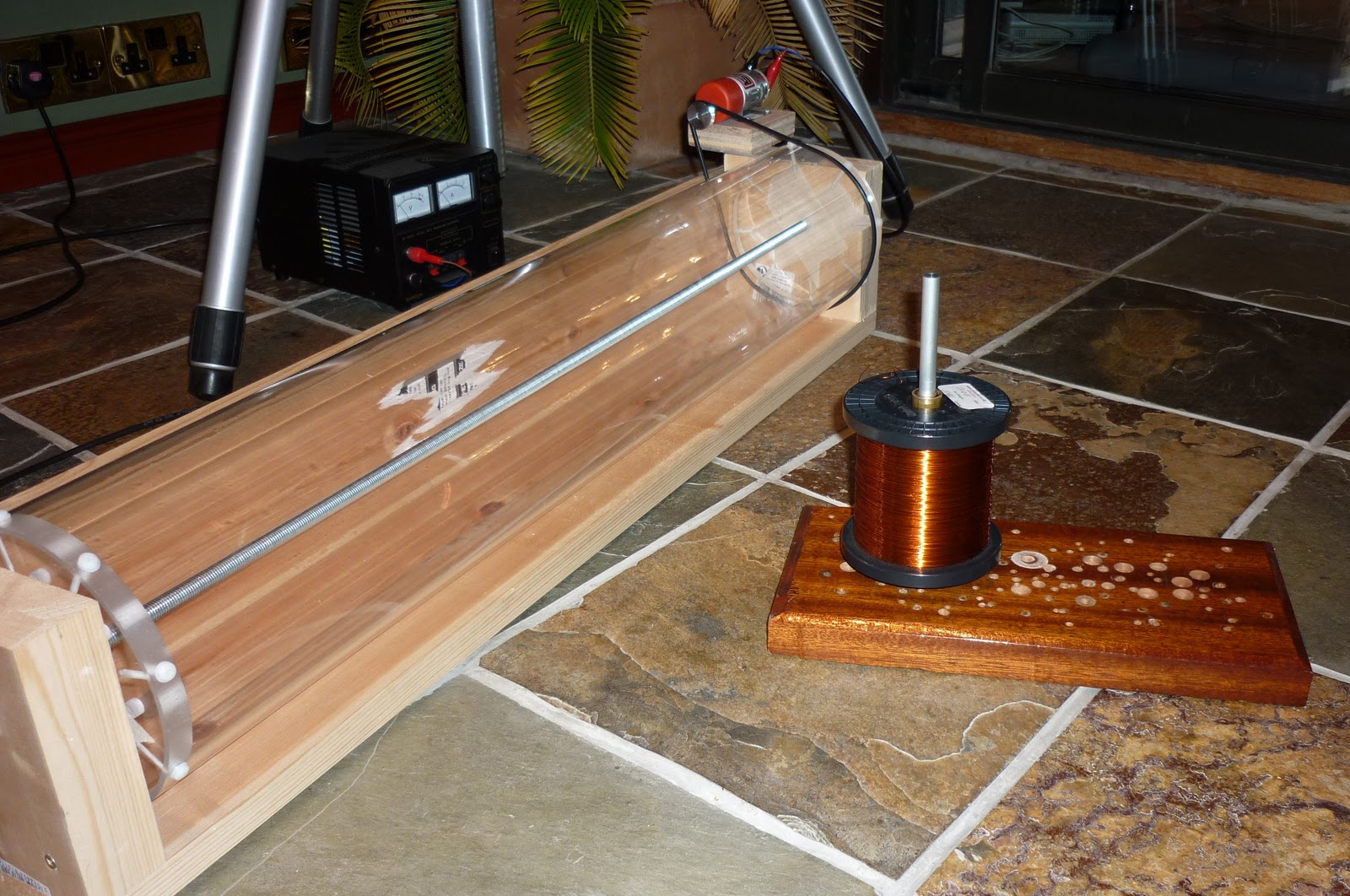
Now that the toroid has finally arrived I am keen to finish off the secondary coil so I can progress on to the primary. The next step is to wind the secondary. The windings will be as per the instructions, 26awg wire which is 0.40mm diameter. When measured with my verniers I get an average of 0.44mm which (I presume) is due to the insulating varnish coating on the wire. The wire will be wound onto my 6" perspex form which measures 810mm. The windings will be 28" high centred on the perspex tube. I will be using my recently upgraded (now motorized) winding jig.
Above you can see the coil former fitted on to the jig. I calculated that there would be just over 1600 turns on the coil each single turn being 471mm (150mm X 3.141) so a total length of 753 metres of wire!
   The winding jig is geared to turn at 15rpm running at a maximum 12 volts so 1600 turns would take 106 minutes minimum.
I started the winding by passing the wire through 3 tiny holes, first in then out then back inside the former, leaving about 6" inside to work with. With the motor running I started to lay down the first few turns. I used my left hand to guide the wire onto the form and a finger nail on my right hand to keep the coils pushed up against each other (if needed). I soon realised that 15rpm was a little fast and backed the bench supply back to 10 volts. Also this is definitely easier as 2 person job. I needed my son (Damien) to help make alterations to rpm, stop and start the jig when the turnings accidently overlap, reposition the feed spool and countless other help during what turned out to be 3 hours of boredom occasionally broken up with moments of intense panic.
The pic above shows the finger nail guide technique which proved to be quite successful. In my left hand you can see a piece of material which I used to create a bit of tension on the wire.
It's best to feed the wire onto the coil slightly behind the present position on the former. This means the last coil on the tube helps guide on the next turn.
Here's a quick video that shows a little of the winding process. Sorry about the annoying noise the winding jig makes. We had to listen to it for 3 hours so think yourself lucky!
We have done a longer video which Damien is going to process and convert into a time lapse. We will post it to youtube and stick a link in here when it's done.


Three hours later and the coil was finished. Could help sticking it in place with the toroid just to get an idea of the finished TC.
Damien's arty shot. We are about to decorate so no comments on the pink flowery wall paper please.

If you like this blog you can show your support by one or all of these.

1. Click on some ads shown on this blog.... I get paid for that.
2. Follow me.... It's good to know someones interested.
3. Leave a comment.... All are appreciated.

Tuesday, 27 September 2011

Second Thoughts

After deciding to upgrade to a 6" secondary coil I got on the phone to Trent Plastics to order the relevant pieces of perspex. These consisted of a 810mm length of 150mm diameter clear acrylic with a 3mm thick wall and two 144mm diameter 15mm thick clear acrylic discs which will be inserted inside the ends of large tube and form the top and base of the secondary coil. I normally deal with a guy called Levi who is always on the ball, I was a little concerned that the discs would not be a good fit inside the 150mm tube due to variations in wall thickness that occurs in extruded acrylic tube so I asked Levi to check the fit of these discs inside the large tube. Three days later and a long cardboard covered tube turned up. I checked the fit of the discs and they were a perfect close push fit inside the large tube.
The above pic shows the 150mm diameter tube, it still has the protective plastic film and I have added masking tape so I can mark the position of the 8 4mm holes that will accept the M4 nylon bolts to locate the top and bottom perspex end caps.
Here are the 2 end caps. They are sitting on a 12mm thick 500mm clear acylic disc which will be the base for the primary coil. The disc on the left is for the bottom of the secondary coil and will be secured to the primary coil base by 8 M8 40mm Nylon bolts. You can see I have already marked the disc for drilling.
The holes need to be drilled to 6.8mm and then tapped for the M8 bolts. This means the bolts will be captive in the secondary coil base which is needed as there will be no access to the bolt heads once the secondary coil is assembled.
Assembled so you get the idea.
The base disc will attach to the secondary coil tube by 8 X 20mm M4 nylon bolts which will be located equidistant around the circumference at a height of 7.5mm.
Starting to get worryingly large!!

Wednesday, 20 July 2011

Looks a bit like ORAC

I have decided to enclose the whole assembly with clear 10mm perspex. Maybe this may help prevent strikes but mainly I just think it will look good. I will have to sort out some ventilation, perhaps a fan mounted in one of the perspex walls, not sure yet. For those of you who remember Blakes 7, I can't help thinking about ORAC as I envisage the finished enclosure.


I am using 10mm square rod as seams on the inside of the side walls which allows me to bolt the box together rather than glueing.


Our glass dinning table made a great flat surface to align the side panels.


- Posted using BlogPress from my iPad

Saturday, 9 July 2011

Terry Filter Safety Gap

Today I picked up a parcel from the local Royal Mail depot. Inside was four long awaited 60mm bolts (should have been 8), least I can make a start on the safety gap. First I need to tap 2 holes through the 2 1" brass balls obtained from Teslastuff.com. The holes need to be 5mm which is the size required if tapping out to M6 with 1.0mm threads. The pic below shows how I mounted them for drilling.


I screwed in the bolt to the existing tapped hole to help me drill at 90 degrees to the existing hole. The bolt also prevented the brass ball spinning in the chuck jaws during drilling. It was easy to find the centre point for drilling as I could spin the work in the chuck to show any mis-alignment. After drilling with the centre drill I drilled a 5mm hole completely through each ball.


Next I tapped the holes out to M6 1.0mm threads. Note the plastic jaw covers on the vice to prevent marking my balls!!!


I then polished my balls by mounting them onto a threaded stud held in the chuck and spinning them up against various grades of emery cloth.


The finished articles almost ready to mount on ceramic insulators on the Terry Filter.


- Posted using BlogPress from my iPad